
Our last lab talked about single area ospf. This ospf multi area configuration lab will walk you though setting up 6 cisco routers in 3 different ospf areas. Due to the fact that the OSPF protocol is a link-state routing protocol, the routers communicate topology data with their closest neighbors. Every router in the AS (autonomous system) has access to the topology data, giving every router in the AS a complete understanding of the topology of the AS.
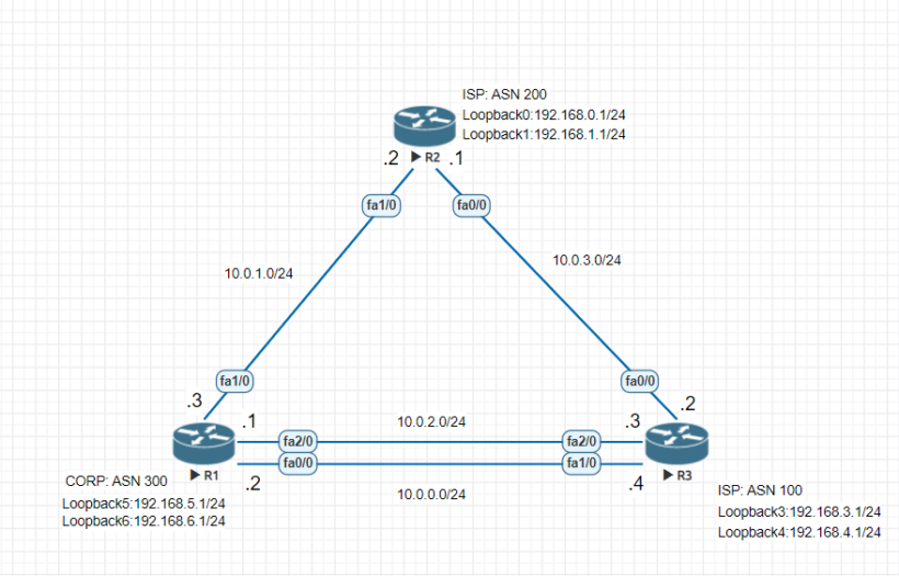
As your network starts to grow so will your topology database. Splitting your routers into separate areas will decrease the size of the topology that the routers will need to know and redistribute. We will use the following topology:
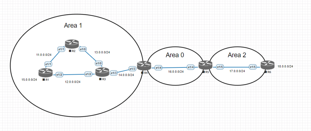
Initial Router and Network Configuration
Since we have a decent amount of interfaces to configure here is a chart of the routers, interface ips and router id’s for ospf.
| Label | Interface | IP | OSPF Router ID | OSPF Area |
|---|---|---|---|---|
| R1 | e1/1 | 11.0.0.1/24 | 1.1.1.1 | area 1 |
| e1/2 | 12.0.0.1/24 | area 1 | ||
| R2 | e1/0 | 13.0.0.2/24 | 2.2.2.2 | area 1 |
| e1/1 | 11.0.0.2/24 | area 1 | ||
| R3 | e1/0 | 13.0.0.3/24 | 3.3.3.3 | area 1 |
| e1/2 | 12.0.0.3/24 | area 1 | ||
| e1/3 | 14.0.0.3/24 | area 1 | ||
| R4 | e1/3 | 14.0.0.4/24 | 4.4.4.4 | area 1 |
| e1/4 | 16.0.0.4/24 | area 0 | ||
| R5 | e1/4 | 16.0.0.5/24 | 5.5.5.5 | area 0 |
| e1/5 | 17.0.0.5/24 | area 2 | ||
| R6 | e1/5 | 17.0.0.6/24 | 6.6.6.6 | area 2 |
| R1 Lan | Loopback0 | 15.0.0.1/24 | ||
| R6 Lan | Loopback0 | 18.0.0.1/24 |
First lets go through and configure each routers hostname and interface ip addresses. The highlighted commands are the important ones needed for each router. On each router just match the interface and ip address together and use the same commands.
Router Configuration
Router>en
Router#conf t
Enter configuration commands, one per line.  End with CNTL/Z.
Router(config)#line con 0
Router(config-line)#logging synchronous
Router(config-line)#exit
Router(config)#hostname R1
R1(config)#int e 1/1
R1(config-if)#ip address 11.0.0.1 255.255.255.0
R1(config-if)#int e 1/2
R1(config-if)#ip address 12.0.0.1 255.255.255.0
R1(config-if)#int range e 1/1 - 2
R1(config-if-range)#no shut
R1(config-if-range)#^Z
R1#copy run start
Destination filename [startup-config]?
Building configuration...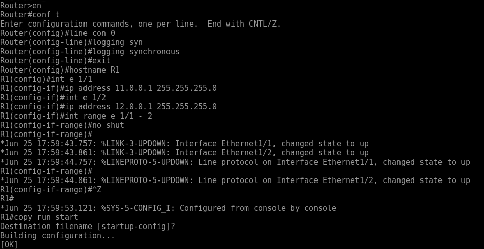
As the interfaces start to come up you will see messages come across the screen. Making sure the interfaces are up is very important to the ospf multi area configuration later on in lab.
Once yo have all the interfaces configured we want to makesure we go back and add our loopback adddresses to simulate our networks. A loopback interface is a virtual interface on a router that is always in an up/up state that can be used for various use cases. For our lab today we will create one for our test lan network on R1 and R6. Then create one on each router for the ospf router ID.
Router Loopback Configuration
On R1 and R6 use the below command to create you simulated LAN networks. Make sure to change the ip address for the corresponding routers network posted above.
R1(config)#interface loopback 0

R1(config-if)#ip address 15.0.0.1 255.255.255.0
While were in the process of creating loopback addresses, lets create all the loopback interfaces for the ospf router ids. The router id helps identify the router in the ospf process so each id needs to be unique. Using the Router IDs listed above, here are the commands to put into each router.
R1#conf t
R1(config)#interface loopback 1
R1(config-if)#ip address 1.1.1.1 255.255.255.255
This way we can explicitly define our router id later in the ospf configuration. This will allow for more structured documentation when troubleshooting network problems.
Ospf multi area configuration steps
Now that we have all of the initial configuration out of the way we can get into getting all of these networks connected. Although all of these networks connect into each other R6 cannot get to R1’s Lan interface. We can test that with a simple ping here.
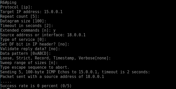
As you can see no connection coming from the 18.0.0.1 address. This is to be expected until we finish the ospf multi area configuration.
Now on each router we will configure the appropriate information below:
- Router ID – the router id helps identify what router you are connecting to. This must be unique
- OSPF Area – the area defines what ospf lsdb the routers interface will participate in.
- Network Commands – network commands will define what interfaces match up to form neighbor relationships
- Passive interfaces – setting passive interfaces will remove the ability to form neighbor relationship off interfaces not intended. Not needed but maybe recommended in a production network
R1 OSPF Configuration
R1#conf t
R1(config)#router ospf 1

R1(config-router)#passive-interface default
R1(config-router)#no passive-interface e 1/2
R1(config-router)#no passive-interface e 1/1
R1(config-router)#network 15.0.0.0 0.0.0.255 area 1
R1(config-router)#network 11.0.0.0 0.0.0.255 area 1
R1(config-router)#network 12.0.0.0 0.0.0.255 area 1
R1(config-router)#^Z
R2 OSPF Configuration
R2#conf t
R2(config)#router ospf 1
R2(config-router)#passive-interface default
R2(config-router)#no passive-interface e 1/0
R2(config-router)#no passive-interface e 1/1
R2(config-router)#router-id 2.2.2.2
R2(config-router)#network 13.0.0.0 0.0.0.255 area 1
R2(config-router)#network 11.0.0.0 0.0.0.255 area 1
R2(config-router)# *Jun 25 22:22:27.004: %OSPF-5-ADJCHG: Process 1, Nbr 1.1.1.1 on Ethernet1/1 from LOADING to FULL, Loadin
g Done
As you can see in the highlighted text above. We have formed a neighbor relationship with ospf router 1.1.1.1 on Ethernet 1/1.
R3 OSPF Configuration
R3(config)#router ospf 1
R3(config-router)#passive-interface default
R3(config-router)#no passive-interface e 1/0
R3(config-router)#no passive-interface e 1/2
R3(config-router)#no passive-interface e 1/3
R3(config-router)#router-id 3.3.3.3
R3(config-router)#network 12.0.0.0 0.0.0.255 area 1
R3(config-router)#network 1.0.0.0 0.0.0.255 area 1
*Jun 27 20:08:58.584: %OSPF-5-ADJCHG: Process 1, Nbr 1.1.1.1 on Ethernet1/2 from LOADING to FULL, Loading Done
R3(config-router)#network 14.0.0.0 0.0.0.255 area 1
R3(config-router)#
*Jun 27 20:09:10.648: %OSPF-5-ADJCHG: Process 1, Nbr 2.2.2.2 on Ethernet1/0 from LOADING to FULL, Loading Done
R3(config-router)#^Z
R3#
We now have all the routers with formed neighbor adjacencies in area 1 configured with ospf. R4 and R5 both are considered ABR (area border routers). These sit at the boundary of area 0 and let ospf know about the different areas.
R4 OSPF multi area Configuration
R4(config)#router ospf 1
R4(config-router)#passive-interface default
R4(config-router)#no passive-interface e 1/3
R4(config-router)#no passive-interface e 1/4
R4(config-router)#router-id 4.4.4.4
R4(config-router)#network 14.0.0.0 0.0.0.255 area 1
R4(config-router)#network 1.0.0.0 0.0.0.255 area 0
*Jun 27 21:06:58.204: %OSPF-5-ADJCHG: Process 1, Nbr 3.3.3.3 on Ethernet1/3 from LOADING to FULL, Loading Done
R4(config-router)#network 16.0.0.0 0.0.0.255 area 0
R5 ABR OSPF multi area Configuration
R5#conf t
R5(config)#router osp
R5(config)#router ospf 1
R5(config-router)#passive-interface default
R5(config-router)#no passive-interface e 1/4
R5(config-router)#no passive-interface e 1/5
R5(config-router)#router-id 5.5.5.5
R5(config-router)#network 16.0.0.0 0.0.0.255 area 0
R5(config-router)#
*Jun 27 21:10:13.080: %OSPF-5-ADJCHG: Process 1, Nbr 4.4.4.4 on Ethernet1/4 from LOADING to FULL, Loading Done
R5(config-router)#network 17.0.0.0 0.0.0.255 area 2
R5(config-router)#^Z
R6 OSPF Configuration
R6#conf t
R6(config)#router ospf 1
R6(config-router)#passive-interface default
R6(config-router)#no passive-interface e 1/5
R6(config-router)#router-id 6.6.6.6
R6(config-router)#network 17.0.0.0 0.0.0.255 area 2

R6(config-router)#network 18.0.0.0 0.0.0.255 area 2
R6(config-router)#^Z
*Jun 27 21:13:14.476: %SYS-5-CONFIG_I: Configured from console by console
*Jun 27 21:13:18.964: %OSPF-5-ADJCHG: Process 1, Nbr 5.5.5.5 on Ethernet1/5 from LOADING to FULL, Loading Done
Multi area ospf confirmation
Now that we have all of the routers in the different areas configured. We will want to run some test to make sure that we have the desired network state. There are a few different commands you can run to test but we will test out some of the various ones here:
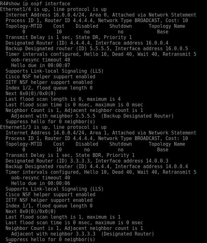
- Show ip ospf interface – view the enabled ospf interfaces
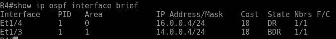
- Show ip ospf interface brief – good for viewing the ospf process associated with the interface and the state
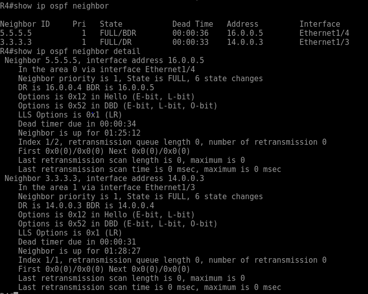
- Show ip ospf neighbor – shows information on the connected ospf neighbors
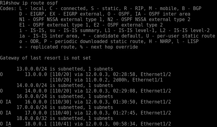
- Show ip route ospf – view routes added by ospf
From R4 when running show ip ospf interface. We get a detailed view of the ospf settings such as the hello, and dead times. Along with the router id’s of the DR and BDR routers. This command can be a simple command to user to find the interfaces that ospf is configured on.
Sometimes this can be a lot of information so to skinny it down the show ip ospf interface brief command gives you a more clear view of what’s going on.
To view and verify the neighbor adjacencies then use the command show ip ospf neighbor [detail]. If you add the detail command after neighbor, you will get a lot more detailed information about that neighbor in your area.
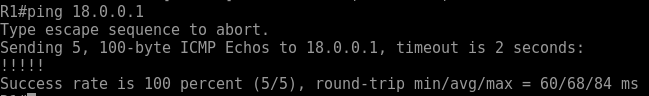
Now that we verified a could commands to make sure that we have some neighbor adjacencies across our different multi area ospf configuration, we can now view some of the routes installed and test that we can reach the other side of the network.
From our topology above you can see that O and O IA routes in our routing table. Any route that is indicated by and O IA means that it crossed and ABR (area boarder router) and we should be able to ping that interface as well from R1 to R6.
Conclusion
This lab took you through the necessary steps to get OSPF up and running in your lab network. This lab is not to be taken as Cisco or Networking best practice, because best practice will always depending on your network. This ospf multi area configuration is a great way to learn our businesses utilize IGP’s such as OSPF to build networks.


Thank you for your work!
Is it mistake in section ‘R3 OSPF Configuration’:
?
Should be 13.0.0.0
Yes your correct. Thanks for the find. I’ll get that updated.