Single area OSPF routing protocol configuration is a very simple setup that can help improve network availability in your network. OSPF (Open Shortest Path First) is a link-state routing protocol based on the Shortest Path First (SPF) algorithm that was created for IP networks. This lab will help you better understand how and why OSPF is setup the way it is.
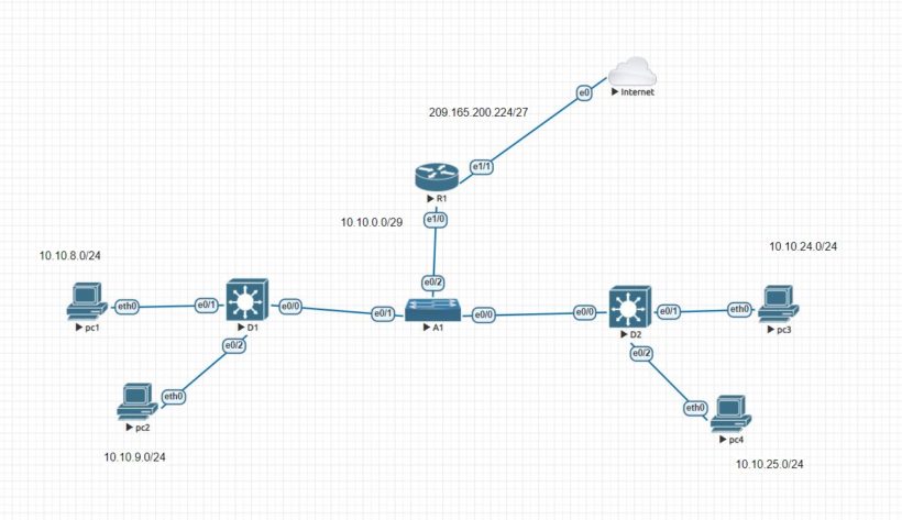
If you have the ability to follow along in this guide, assemble your network design with how the picture above is configured. This design does use 2 layer 3 switches to show how a layer 3 switch can provide layer 3 routing access as well. Depending on the model you use or version, the commands may be different.
| Device | Interface | Ipv4 Address |
|---|---|---|
| R1 | Ethernet 1/0 | 10.10.0.1/29 |
| Loopback0 | 209.165.200.225/27 | |
| Loopback1 | 192.168.1.1/26 | |
| D1 | Ethernet 0/0 | 10.10.0.2/29 |
| Ethernet 0/1 | 10.10.8.1/24 | |
| Ethernet 0/2 | 10.10.9.1/24 | |
| D2 | Ethernet 0/0 | 10.10.0.3/29 |
| Ethernet 0/1 | 10.10.24.1/24 | |
| Ethernet 0/2 | 10.10.25.1/24 | |
| PC1 | Nic | 10.10.8.10/24 |
| PC2 | Nic | 10.10.9.10/24 |
| PC3 | Nic | 10.10.24.10/24 |
| PC4 | Nic | 10.10.25.0/24 |
Part 1: Single Area OSPF Configuration
In this part of the lab implement single area ospf across the multiaccess ethernet network. OSPF can be enabled either using the traditional network router config command and wild card mask. The wildcard lets you be as specific or vague as you need. Here area couple of examples:
- network ip-address 0.0.0.0 area area-id – allows you to configure the network statement with an IP address explicitly for OSPF on that interface
- network network wildcard-mask area area-id – You can match the wildcard mask explicitly with a subnet or be less specific to match several subnets.
- network 0.0.0.0 255.255.255.255 area area – This setup is the vaguest method because this wildcard with 0.0.0.0 matches all interfaces
Another way to configure ospf is using the ip ospf process-id area area-id command on the interface but this method can increase complexity as the number of interfaces starts to increase.
step 1: implement OSPF on D1 using Explicit IP addresses
D1 will advertise its OSPF networks using OSPF Network ip-address 0.0.0.0 area-id command. When using the 0.0.0.0 wildcard mask it will only enable ospf on the exact interface that matches the ip address. The picture below shows the exact commands to configure Layer 3 Switch D1.
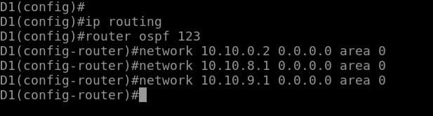
Here is an explanation of what is going on with each of the commands above in the configuration.
- since this is a layer 3 switch we must enable routing by using the command ip routing
- next we enter ospf configuration mode using the command ospf 123. The process id does not have to match other routers in the same area
- next we configure ospf only for each interface that the ip addresses sit on. That is why we used the 0.0.0.0 wildcard mask.
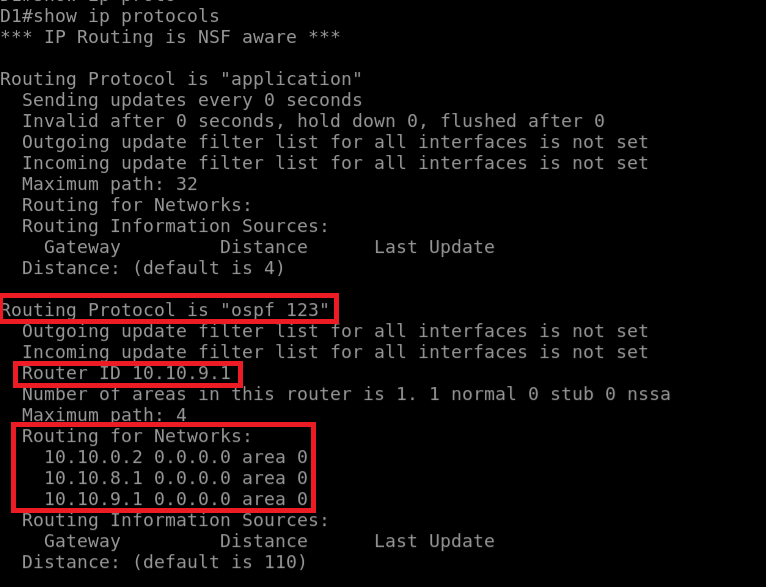
We can now verify the ospf configuration on D1 using the show ip protocols command. The OSPF router ID is chosen because its the highest active ipv4 address configured. There are ways to set that manually as well. In the routing for networks, we can see the networks that are advertising on the D1 networks.
step 2: Implement OSPF on D2 using wildcard masks
- Like D1 we must enable ip routing using the ip routing command
- Next we must enter ospf configuration mode. remember the process ids do not have to match but it makes it easier to remember. So we will issue the command router ospf 123
- To find your wildcard mask you take 255.255.255.255 and subtract that from your subnet mask for your network. For the 255.255.255.248 subnet we get a wildcard of 0.0.0.7. We will use that for our ospf network command network 10.10.0.0 0.0.0.7 area 0
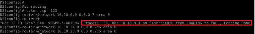
- As you can see, the router has formed a neighbor relationship with router D1 on Ethernet 0/0 with the neighbor 10.10.9.1 which is that routers router-id
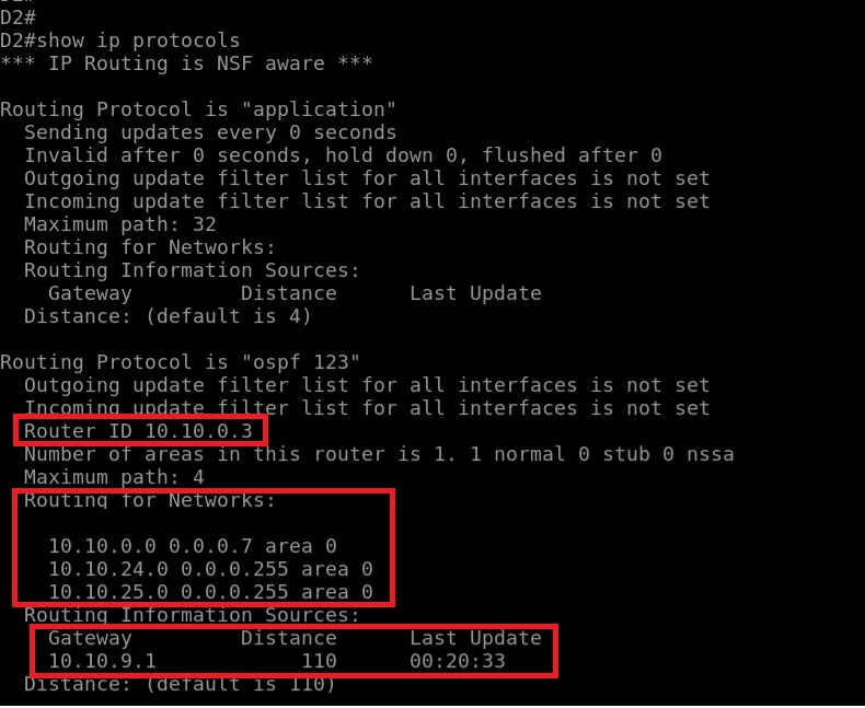
- Lets now verify the OSPF routing protocol configuration for D2 using the show ip protocols. We can see that the router ID for D2 is 10.10.0.3 and we are routing for the needed networks now.
step 3: Configure OSPF on R1 using the interface specific method
The interface specific method is easy because it does not require you to put in any network statements or wildcard mask. From our R1 configuration the loopback 1 interface is only configured to simulate another network. Default behavior for OSPF is to advertise a 32 bit host route for a loopback interface. To make sure the /26 network is advertised we will issue the command ip ospf network point-to-point.
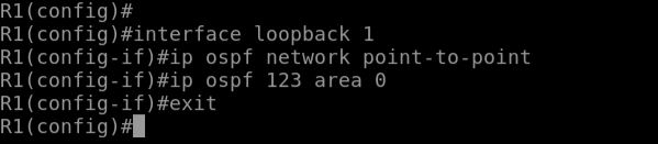
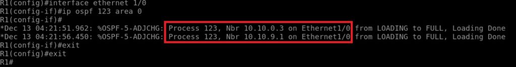
Since we are already on the interface we can issue the command ip ospf 123 area 0 which now allows us to advertise ospf on that interface. We will also setup the same configuration on interface ethernet 1/0. We will see all the neighbor relationships start to form as well with the other routers.
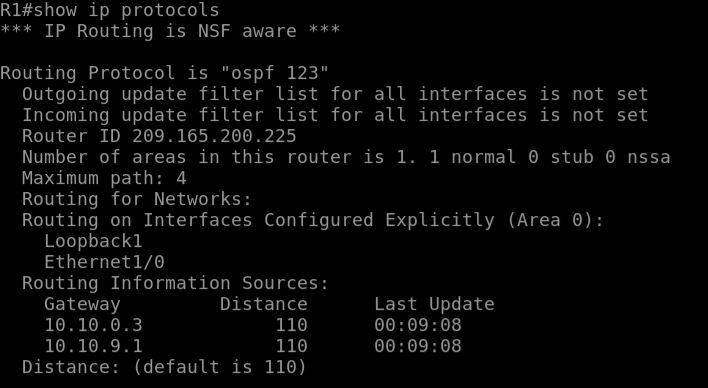
We now can issue the show ip protocols to view the status of the ospf configuration.
step 4: Assign OSPF router IDs to R1, D1, and D2
Router Id’s are dynamically assigned in order of preference depending on specific configurations or can be assigned manually. Here are 3 ways an OSPF router ID can be assigned:
- Manually configured using the router-id router-id router configuration command
- If no router-id is configured manually then the highest enabled loopback IP address is used as the router ID.
- If no loopback interfaces configured then the highest IP address of any active physical in the up state becomes the Router ID when the OSPF process initializes.
It is best to assign a static OSPF router-id for troubleshooting purposes. The OSPF process must be reset using the clear ip ospf process command.
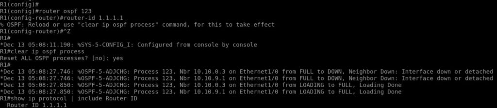
As you can see the new router ID has been applied for this router and cleared to allow the new router ID to take place. This same process will be repeated on Router D1 and D2.
step 5: Verify OSPF routing protocol configuration
Now that we have OSPF running on all the routers in the lab we need to make sure we know how to validate that OSPF is operating as configured. Along with the show ip protocols command we have been running, there other useful commands to remember.
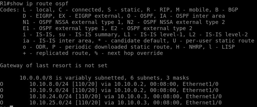
- show ip route ospf is used to verify the operation of OSPF. OSPF routers will display an O next to them, lists the administrative distance, Assigned metric, next-hop IP address, and the local exit interface to reach the network. From the picture below we have 4 networks we can get to with and administrative distance of 110 going out the Ethernet 1/0 interface.
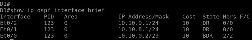
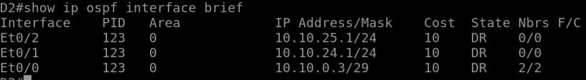
- Show ip ospf interface brief command will show which interfaces are enabled for OSPF, process ID, area ID, and state. A missing interface could be the indication of a incorrect network statement, IP addressing problem, or disabled interface.
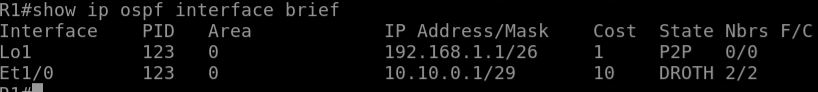
As you can see we have a couple different State Acronyms such as DR, BDR, DROTH, and P2P.
- DR: Designated router which this interface is connected. The DR establishes OSPF adjacencies with all other routers on the network.
- BDR: Backup designated Router on the multiaccess network to which this interface is connected. Like the DR, the BDR establishes adjacensies with all other routers on the broadcast network.
- DROTH: Its neither the DR nor the BDR on the network. All non DRs and BDRs on the broadcast network would be DROTHERs and establish adjacencies only with the DR and BDR.
- P2P: This is an OSPF point-to-point interface and does not require a DR or BDR. In this state, the interface is fully functional and starts exchanging hello packets with all of its neighbors.
To verify which OSPF neighbor your device has established adjacencies with, the state and next-hop IP address you can use the command show ip ospf neighbor [detail] command. Some other validation commands include show ip ospf, show ip ospf topology-info, show ip ospf database.
Part 3: Configure and verify the advertising of a Default Route
In this part we will configure a default static route to the internet R1. R1 will then propagate the default route to the other OSPF routers as an external Type 2 OSPF route. This is the most efficient method to provide a consistent default route.
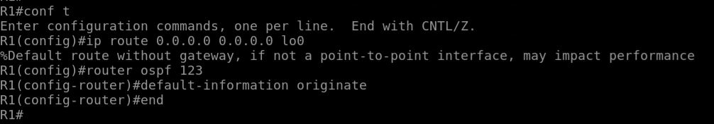
- First configure default route advertisement on R1. Issue the command ip route 0.0.0.0 0.0.0.0 lo0
- Enter ospf configuration and use the default-information originate
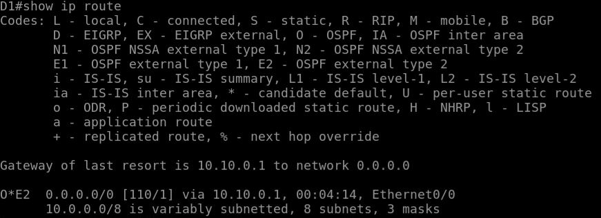
Checking Router D1 and D2 will show that we now have a default route to 10.10.0.1 to get out to the internet.
If you completed this lab you will have a great understanding of how to configure OSPF using various methods. In most network environments you could enable OSPF without much customization and it will work great. There may be times where you may need to add advanced tuning features and that is something we will discuss in our next topic.