Now that we’ve completed parts 1 and 2, we can wrap up this lab by implementing router-based inter-vlan routing and looking at some CAM and CEF details. Rather than use a layer 3 switch and configuring switch virtual interfaces to route packets across vlans, we’ll utilize a router to accomplish the job and deliver packets across vlans using sub interfaces and trunk ports.
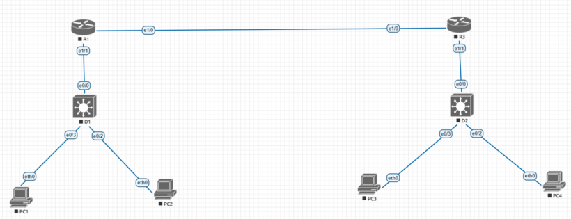
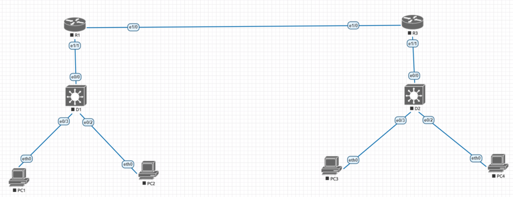
Cisco lab topology
| Device | interface | ipv4 address | ipv6 address | ipv6 link-local |
| R1 | e 1/1 | 10.1.13.1/24 | 2001:db8:acad:10d1::1/64 | fe80::1:1 |
| e 1/0 | 10.1.3.1/24 | 2001:db8:acad:1013::1/64 | fe80::1:2 | |
| D1 | e 0/0 | 10.1.13.13/24 | 2001:db8:acad:10d1::d1/64 | fe80::d1:1 |
| VLAN50 | 10.2.50.1/24 | 2001:db8:acad:1050::d1/64 | fe80::d1:2 | |
| VLAN60 | 10.2.60.1/24 | 2001:db8:acad:1060::d1/64 | fe80::d:3 | |
| R3 | e 1/0 | 10.1.3.3/24 | 2001:db8:acad:1013::3/64 | fe80::3:1 |
| e 1/1.75 | 10.3.75.1/24 | 2001:db8:acad:3075::1/64 | fe80::3:2 | |
| e 0/1.85 | 10.3.85.1/24 | 2001:db8:acad:3085::1/64 | fe80::3:3 | |
| D2 | VLAN75 | 10.3.75.14/24 | 2001:db8:acad:3075::d2/64 | fe80::d2:1 |
| PC1 | NIC | 10.2.50.50/24 | 2001:db8:acad:1050::50/64 | EUI-64 |
| PC2 | NIC | 10.2.60.50/24 | 2001:db8:acad:1060::50/64 | EUI-64 |
| PC3 | NIC | 10.3.75.50/24 | 2001:db8:acad:3075::50/64 | EUI-64 |
| PC4 | NIC | 10.3.85.50/24 | 2001:db8:acad:3085::50/64 | EUI-64 |
Step 1.
We’ll begin by connecting to the D2 switch on the bottom right side of the configuration. We’ll start by setting up all of the necessary configurations to support vlans between the switch and the devices.
a. lets begin by setting up the D2 switch with any needed vlans. Once the vlans are created we will assign the ports that the machines will be in to those ports.
D2 (config)# vlan 75
D2 (config-vlan)# name Group75
D2 config-vlan)# exit
D2 (config)# vlan 85
D2 (config-vlan)# name Group85
D2 (config-vlan)# exit
D2 (config)# vlan 999
D2 (config-vlan)# name NativeVLAN
D2 (config-vlan)# exit
b. now that we have the vlans configured, next we will assign the appropriate ports to each vlan
D2 (config)# interface e0/3
D2 (config-if)# switchport mode access
D2 (config-if)# switchport access vlan 75
D2 (config-if)# no shutdown
D2 (config-if)# exit
D2 (config)# interface e0/2
D2 (config-if)# switchport mode access
D2 (config-if)# switchport access vlan 85
D2 (config-if)# no shutdown
D2 (config-if)# exit
c. even though its not needed we can create a svi (switched virtual interface) that will sit inside of vlan 75. This could be setup to be used as an interface to manage the switch on.
D2 (config)# interface vlan 75
D2 (config-if)# ip address 10.3.75.14 255.255.255.0
D2 (config-if)# ipv6 address 2001:db8:acad:3075::d2/64
D2 (config-if)# no shutdown
D2 (config-if)# exit
d. Because we’ll be sending vlan tags up to the router to be processed, we’ll need to set up a trunk port so we can tag the relevant vlans based on the ports they’ll be processed on. Multiple vlans cannot communicate over a single port without the use of a trunk port. In a networking context, it’s also best to specify the native vlan as something other than vlan 1, because all devices by default join up to vlan 1. Also, specify only the vlans that are authorized to communicate with the “allowed vlan command” to help improve security for vlans that can go via the trunk port.
D2 (config)# interface e 0/0
D2 (config-if)# switchport mode trunk
D2 (config-if)# switchport trunk native vlan 999
D2 (config-if)# switchport trunk allowed vlan 75, 85, 999
D2 (config-if)# no shutdown
D2 (config-if)# exit
Step 2.
Now that we have switch D2 configured all the way with the correct vlan configurations we can start to move on to connecting everything by configuring R3 and all the router configurations. R3 will be were we will create the needed subinterfaces to route between the needed vlans.
R3(config)# interface e 1/1
R3(config-if)# no shutdown
R3(config-if)# exit
R3(config)# interface e 1/1.75
R3(config-subif)# encapsulation dot1q 75
R3(config-subif)# ip address 10.3.75.1 255.255.255.0
R3(config-subif)# ipv6 address fe80::3:2 link-local
R3(config-subif)# ipv6 address 2001:db8:acad:3075::1/64
R3(config-subif)# no shutdown
R3(config-subif)# exit
R3(config)# interface e 1/1.85
R3(config-subif)# encapsulation dot1q 85
R3(config-subif)# ip address 10.3.85.1 255.255.255.0
R3(config-subif)# ipv6 address fe80::3:3 link-local
R3(config-subif)# ipv6 address 2001:db8:acad:3085::1/64
R3(config-subif)# no shutdown
R3(config-subif)# exit
R3(config)# interface e 1/1.999
R3(config-subif)# no shutdown
R3(config-subif)# exit
R3(config)# interface e 1/0
R3(config-if)# ip address 10.1.3.3 255.255.255.0
R3(config-if)# ipv6 address fe80::3:1 link-local
R3(config-if)#ipv6 address 2001:db8:acad:1013::3/64
R3(config-if)# no shutdown
R3(config-if)# exit
R3(config)# ip route 0.0.0.0 0.0.0.0 10.1.3.1
R3(config)# ipv6 route ::/0 2001:db8:acad:1013::1
c. All that remains is to assign an IP address to each computer or device connected to the switch. Now that we’ve built up the full environment, we can begin testing.
Assign pc3 the 10.3.75.1 for the ipv4 address and the 2001:db8:acad:3075::1 then assign pc4 10.3.85.1 and 2001:db8:acad:3085:1. Test ping one pc to the other to make sure all configurations to the other side are correct.