The goal of this lab is to assist you in creating inter-vlan routing with a layer 3 switch on one network and a router on a stick configuration on another. Check out my video below for a live explanation on how to setup this lab. As a networker, you may be requested to segment parts of your network from others for a variety of reasons, including security, traffic optimization, testing and more. Inter-vlan routing allows you to expand your network’s capabilities without spending a lot of money on new hardware.
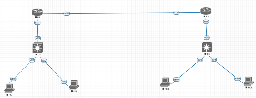
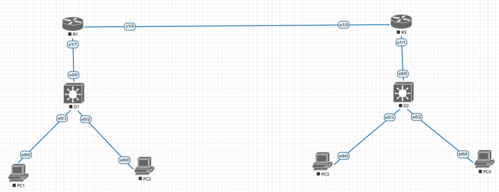
Cisco inter-vlan routing topology
| Device | interface | ipv4 address | ipv6 address | ipv6 link-local |
| R1 | e 1/1 | 10.1.13.1/24 | 2001:db8:acad:10d1::1/64 | fe80::1:1 |
| e 1/0 | 10.1.3.1/24 | 2001:db8:acad:1013::1/64 | fe80::1:2 | |
| D1 | e 0/0 | 10.1.13.13/24 | 2001:db8:acad:10d1::d1/64 | fe80::d1:1 |
| VLAN50 | 10.2.50.1/24 | 2001:db8:acad:1050::d1/64 | fe80::d1:2 | |
| VLAN60 | 10.2.60.1/24 | 2001:db8:acad:1060::d1/64 | fe80::d:3 | |
| R3 | e 1/0 | 10.1.3.3/24 | 2001:db8:acad:1013::3/64 | fe80::3:1 |
| e 1/1.75 | 10.3.75.1/24 | 2001:db8:acad:3075::1/64 | fe80::3:2 | |
| e 0/1.85 | 10.3.85.1/24 | 2001:db8:acad:3085::1/64 | fe80::3:3 | |
| D2 | VLAN75 | 10.3.75.14/24 | 2001:db8:acad:3075::d2/64 | fe80::d2:1 |
| PC1 | NIC | 10.2.50.50/24 | 2001:db8:acad:1050::50/64 | EUI-64 |
| PC2 | NIC | 10.2.60.50/24 | 2001:db8:acad:1060::50/64 | EUI-64 |
| PC3 | NIC | 10.3.75.50/24 | 2001:db8:acad:3075::50/64 | EUI-64 |
| PC4 | NIC | 10.3.85.50/24 | 2001:db8:acad:3085::50/64 | EUI-64 |
Lab objectives
To make this lab more readable, we’ll go over how to set it up in four steps. Throughout the tutorial, I will explain what each configuration entered implies so that you can grasp the significance of each operation.
- Part 1 will include building out the network and configuring the basic device settings
- Part 2 we will configure inter-vlan routing on a layer 3 switch
- Part 3 we will setup router-based inter-vlan routing which is usually called router on a stick for us nerds
- Part 4 we will examine the CAM (content-addressable memory) table and CEF (cisco express forwarding)
Lab resources
If your using any type of emulation software such as eve-ng, gns3, or packet tracer you can use the following list of device types to follow along yourself
- 2 cisco routers
- 2 cisco switches with one switch being layer 3 capable meaning it can router packets
- 4 pcs (these can be switches with an interface with a specific ip address
- console cable or some particular way you will interface with the machines
Part 1: Building out the Cisco Network and configuring the basic device settings
Step1.
take a look at the picture above and connect all of the cisco devices together accordingly so that the configuration setup goes more smoothly
Step 2.
Lets start to configure the basic settings for each networking device. Lets start with the two routers and move down into the switches. The config on each devices is pretty standard. the no ip domain lookup tells the device
Router R1
no ip domain lookup
hostname R1
line con 0
exec-timeout 0 0
logging synchronous
exit
banner motd # This is R1 Inter-vlan routing #
exit
copy run start
Router R3
no ip domain lookup
hostname R3
line con 0
exec-timeout 0 0
logging synchronous
exit
banner motd # This is R3 Inter-vlan routing #
exit
copy run start
Switch D1
no ip domain lookup
hostname D1
line con 0
exec-timeout 0 0
logging synchronous
exit
banner motd # This is Switch D1 Inter-vlan routing #
exit
copy run start
Switch D2
no ip domain lookup
hostname D1
line con 0
exec-timeout 0 0
logging synchronous
exit
banner motd # This is Switch D2 Inter-vlan routing #
exit
copy run start
Part 2: How to setup and configure inter-vlan routing on a layer 3 switch
We’ll concentrate on the arrangement on the left side of the diagram in this phase of the lab. Instead of sending data up to the router, a layer 3 switch may route packets, allowing us to do all of the routing closer to the targets. If you want to make sure that IPv6 is supported, execute the command “show sdm prefer” and make sure that the “number of unicast routes” supported is not zero. If that’s the case, you can concentrate solely on IPv4 addresses in the lab.
Step 1.
on Switch D1 we will configure everything that’s needed for inter-vlan routing
a. First we need to allow switch D1 to support ip routing and ipv6 unicast routing if it supports ipv6.
D1 (config)# ip routing
D1 (config)#ipv6 unicast routing
b. Next we need to create VLANS and name them as specified in the topology or to your liking. (the naming is more to keep the configuration and documentation clean)
D1 (config)# vlan 50
D1 (config-vlan)# name Group50
D1 (config-vlan)# exit
D1 (config)# vlan 60
D1 (config-vlan)# name Group60
D1 (config-vlan)# exit
c. Now we need to assign the e0/3 to Vlan 50 and e0/2 to Vlan 60 to separate them, so we are going to make sure each port is an access port and configure for the correct vlan
D1 (config)# interface e0/3
D1 (config-if)# switchport mode access
D1 (config-if)# switchport access vlan 50
D1 (config-if)# no shutdown
D1 (config-if)# exit
D1 (config)# interface e0/2
D1 (config-if)# switchport mode access
D1 (config-if)# switchport access vlan 60
D1 (config-if)# no shutdown
D1 (config-if)# exit
d. After that we want to create virtual interfaces on the layer 3 switch to create the ability to route the packets. These interfaces are called SVI or (switch virtual interfaces)
D1 (config)# interface vlan 50
D1 (config-if)# ip address 10.2.50.1 255.255.255.0
D1 (config-if)# ipv6 address fe80::d1:2 link-local
D1 (config-if)# ipv6 address 2001:db8:acad:1050::d1/64
D1 (config-if)# no shutdown
D1 (config-if)# exit
D1 (config)# interface vlan 60
D1 (config-if)# ip address 10.2.60.1 255.255.255.0
D1 (config-if)# ipv6 address fe80::d1:3 link-local
D1 (config-if)# ipv6 address 2001:db8:acad:1060::d1/64
D1 (config-if)# no shutdown
D1 (config-if)# exit
e. If you haven’t previously done so, we now have four PC devices that require an IP address. Configure your computers in accordance with the table above, using the right IP address information and connecting to the relevant ports. Ping all of the devices after you’ve set up the computers. If you can connect to machines in the other vlan, we’ve set up inter-vlan routing successfully. Security can also be used to prevent routing over, but that is a different topic.
Step 2.
We’ll set the port e0/0 up as a routed port and establish the default routes because this will be uplinking to a router and will not be used as an access port.
D1 (config)# interface e0/0
D1 (config-if)# no switchport
D1 (config-if)# ip address 10.1.13.13 255.255.255.0
D1 (config-if)# ipv6 address fe80::d1:1 link-local
D1 (config-if)# ipv6 address 2001:db8acad:10d1::d1/64
D1 (config-if)# no shutdown
D1 (config-if)# exit
D1 (config)# ip route 0.0.0.0 0.0.0.0 10.1.13.1
D1 (config)# ipv6 route ::/0 2001:db8:acad:10d1::1
Step 3.
We now need to configure the interface addressing and static routing for router R1
R1 (config)# ipv6 unicast-routing
R1 (config)# interface e1/1
R1 (config-if)# ip address 10.1.13.1 255.255.255.0
R1 (config-if)# ipv6 address fe80::1:1 link-local
R1 (config-if)# ipv6 address 2001:db8:acad:10d1::1/64
R1 (config-if)# no shutdown
R1 (config-if)# exit
R1 (config)# interface e1/0
R1 (config-if)# ip address 10.2.0.0 255.255.255.0
R1 (config-if)# ipv6 address fe80::1:2 link-local
R1 (config-if)# ipv6 address 2001:db8:acad:1013::1/64
R1 (config-if)# no shutdown
R1 (config-if)# exit
this last section for parts 1 & 2 will setup routing on R1 for the networks supported by D1 to point at R3.
R1 (config)# ip route 10.2.0.0 255.255.0.0 10.1.13.13
R1 (config)# ipv6 route 2001:db8:acad:1050::/64 2001:db8:acad:10d1::d1
R1 (config)# ipv6 route 2001:db8:acad:1060::/64 2001:db8:acad:10d1::d1
R1 (config)# ip route 0.0.0.0 0.0.0.0 10.1.3.3
R1 (config)# ipv6 route ::/0 2001:db8:acad:1013::1
once you are done going through this side of the network’s configuration we will move over to the other side to setup connecting all the dots. Click Here to to go Part 3&4