Cisco Spanning tree protocol lab details
The implications of a loop in a layer 2 network can have a big impact on the network’s reliability. When loops arise, the host and linked equipment may be unable to work properly, resulting in a significant reduction in business uptime. Layer 2 loops can be avoided by following sound design practices and adopting the Cisco spanning tree protocol.
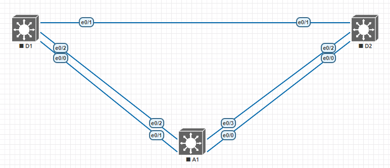
We’ll use a setup of three switches connected to each other in this experiment, with multiple connections set up between two devices. Although my topologies, connections, and ports may differ, you can achieve comparable findings by using packet tracer, gns3, and other similar tools with three switches of your own. Below are the ip address scheme used for this lab.
| Device | Interface | Ipv4 Address |
| D1 | VLAN1 | 10.0.0.1/8 |
| D2 | VLAN1 | 10.0.0.2/8 |
| A1 | VLAN1 | 10.0.0.3/8 |
Part 1: configuring basic switch and interface settings
Before we get into any high-level detail on configuring the spanning tree protocol, we’re first going to set up the three switches with some basic configurations such as VLAN, trunk, and IP address settings. Let’s first start off with going into Switch D1 and configuring the below commands inside of global configuration mode.
Step1: configuring cisco spanning tree protocol on switch D1
Switch (config)# hostname D1
D1 (config)# spanning-tree mode pvst
D1 (config)# banner motd # D1, stp topology #
D1 (config)# line con 0
D1 (config-line)# exec-timeout 0 0
D1 (config-line)# logging synchronous
D1 (config-line)# exec-timeout 0 0
D1 (config-line)# exit
D1 (config)# interface range e 0/0-3
D1 (config-if-range)# shutdown
D1 (config-if-range)# exit
D1 (config)# interface range e 0/0-2
D1 (config-if-range)# switchport trunk encapsulation dot1q
D1 (config-if-range)# switchport mode trunk
D1 (config-if-range)# no shutdown
D1 (config-if-range)# exit
D1 (config)# vlan 2
D1 (config-vlan)# name secondvlan
D1 (config-vlan)# exit
D1 (config)# interface vlan 1
D1 (config-if)# ip address 10.0.0.1 255.0.0.0
D1 (config-if)# no shut
D1 (config-if)# exit
Step2: configuring cisco spanning tree protocol on switch D2
Switch (config)# hostname D2
D2 (config)# spanning-tree mode pvst
D2 (config)# banner motd # D2, stp topology #
D2 (config)# line con 0
D2 (config-line)# exec-timeout 0 0
D2 (config-line)# logging synchronous
D2 (config-line)# exec-timeout 0 0
D2 (config-line)# exit
D2 (config)# interface range e 0/0-3
D2 (config-if-range)# switchport trunk encapsulation dot1q
D2 (config-if-range)# switchport mode trunk
D2 (config-if-range)# no shutdown
D2 (config-if-range)# exit
D2 (config)# vlan 2
D2 (config-vlan)# name secondvlan
D2 (config-vlan)# exit
D2 (config)# interface vlan 1
D2 (config-if)# ip address 10.0.0.2 255.0.0.0
D2 (config-if)# no shut
D2 (config-if)# exit
Step 3: configuring cisco spanning tree protocol on switch A1
Switch (config)# hostname A1
A1 (config)# spanning-tree mode pvst
A1 (config)# banner motd # A1, stp topology #
A1 (config)# line con 0
A1 (config-line)# exec-timeout 0 0
A1 (config-line)# logging synchronous
A1 (config-line)# exec-timeout 0 0
A1 (config-line)# exit
A1 (config)# interface range e 0/0-3
A1 (config-if-range)# shutdown
A1 (config-if-range)# exit
A1 (config)# interface range e 0/0-2
A1 (config-if-range)# switchport trunk encapsulation dot1q
A1 (config-if-range)# switchport mode trunk
A1 (config-if-range)# no shutdown
A1 (config-if-range)# exit
A1 (config)# vlan 2
A1 (config-vlan)# name secondvlan
A1 (config-vlan)# exit
A1 (config)# interface vlan 1
A1 (config-if)# ip address 10.0.0.3 255.0.0.0
A1 (config-if)# no shut
A1 (config-if)# exit
Step 4:
Now that we have all of the devices configured and powered on we need to determine a few important spanning-tree characteristics from each switch. To get the current spanning tree configuration, navigate to enable mode and type in show spanning-tree. It will be helpful to draw out the topology where the root, designated, and alternate ports are on each VLAN segment. The image below shows each switch and its VLAN configuration.
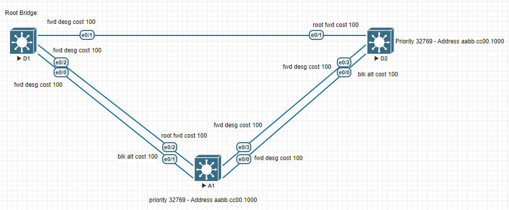
All spanning-tree calculations use the root bridge as a reference point to identify whether redundant paths should be blocked. The root bridge switch is chosen using an election process. Switch D1 is the current root bridge for VLAN 1 & 2 and as you can see each switch besides the root bridge has a particular port that is blocking when not active to prevent the ability for loops to happen.
Here are a couple of definitions to take note of when going through this first part of the lab and looking at the topology above
- Root Bridge – The root bridge serves as a reference point for all spanning-tree calculations to determine which redundant paths to block. An election process determines which switch becomes the root bridge.
- Forwarding Port – Frames are forwarded across the associated network segment by a port in the forwarding state. The port will process BPDUs, update its MAC Address database with frames it receives, and forward user traffic through the port while it is in the forwarding mode. The usual state is the forwarding state.
- Root Port – From the switch to the Root Bridge, the Root Port is the port on the Bridge (Switch) with the lowest Spanning Tree Path Cost.
- Blocking Port – When user data is stopped from entering or exiting a port, it is considered blocked.
- Root Primary command – The switch’s priority is set to a predetermined value of 24,576, or the maximum multiple of 4096 less than the network’s lowest bridge priority.
In some network solutions you may not want the switches to pick the root bridge by itself in the event it picks the least optimal. We are going to implement a couple of configuration changes in Part 2 of this lab to the above topology to give us the needed root bridge configuration. Take some time to go through the above configuration in your lab and then head over to part 2 for the next steps in spanning tree protocol tuning.