By default all routers and switches on a router are included in the global routing table. For service providers to help support multiple customers, they must be able to virtualize the router to create multiple virtual routing tables using VRF but in our case for this Lab VRF-Lite. VRF-Lite just removes the needs to implement the MPLS component.
VRF-Lite lab build requirements
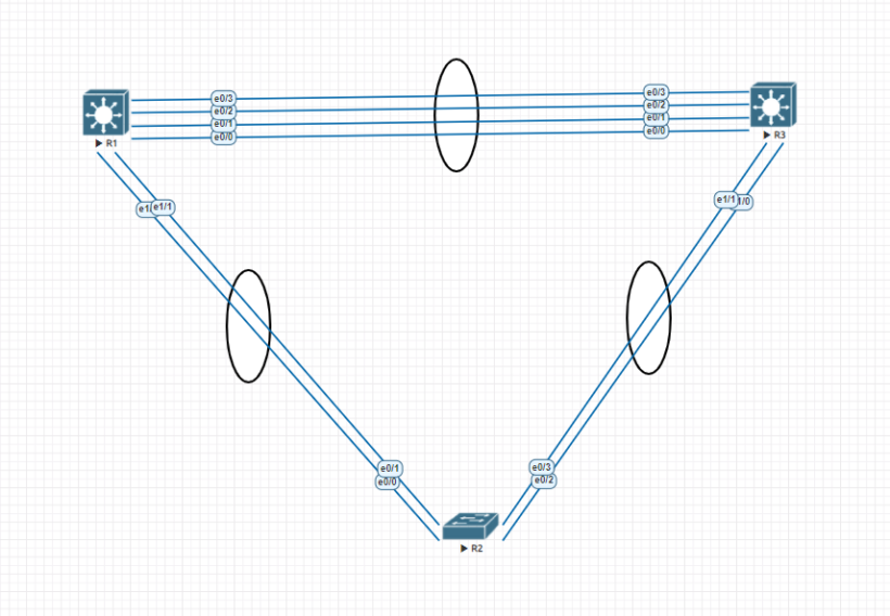
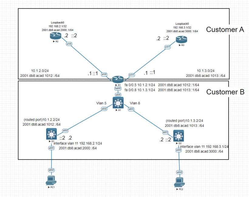
To effectively get the most out of this lab we will need 3 routers and 3 switches. 2 routers will sit on the customer A side and 1 router will sit between customer A and customer B. We will use 1 switch to act as a layer 2 switch that will connect up the 2 other switches to the router’s sub interfaces for each vlan. Follow the steps below for implementing the connections for all of the equipment.
Part 1: Build the network and configure basic device settings
Router R1 Configuration
- enable
- configure terminal
- hostname R1
- no ip domain lookup
- ipv6 unicast-routing
- line con 0
- exec-timeout 0 0
- logging synchronous
- exit
- line vty 0 4
- privilege level 15
- password cisco123
- exec-timeout 0 0
- logging synchronous
- login
- exit
Router R2 Configuration
- enable
- configure terminal
- hostname R2
- no ip domain lookup
- ipv6 unicast-routing
- line con 0
- exec-timeout 0 0
- logging synchronous
- exit
- line vty 0 4
- privilege level 15
- password cisco123
- exec-timeout 0 0
- logging synchronous
- login
- exit
- interface ethernet 1/0
- ip address 10.1.2.2 255.255.255.0
- ipv6 address fe80::2:1 link-local
- ipv6 address 2001:db8:acad:1012::2/64
- no shutdown
- exit
- interface loopback 0
- ip address 192.168.2.1 255.255.255.255
- ipv6 address fe80::2:2 link-local
- ipv6 address 2001:db8:acad:2000::1/64
- exit
- ip route 0.0.0.0 0.0.0.0 ethernet 1/0 10.1.2.1
- ipv6 route ::/0 ethernet 1/0 2001:db8:acad:1012::1
Router R3 Configuration
- enable
- configure terminal
- hostname R3
- no ip domain lookup
- ipv6 unicast-routing
- line con 0
- exec-timeout 0 0
- logging synchronous
- exit
- line vty 0 4
- privilege level 15
- password cisco123
- exec-timeout 0 0
- logging synchronous
- login
- exit
- interface ethernet 1/1
- ip address 10.1.3.2 255.255.255.0
- ipv6 address fe80::3:1 link-local
- ipv6 address 2001:db8:acad:1013::2/64
- no shutdown
- exit
- interface loopback 0
- ip address 192.168.3.1 255.255.255.255
- ipv6 address fe80::3:2 link-local
- ipv6 address 2001:db8:acad:3000::1/64
- exit
- ip route 0.0.0.0 0.0.0.0 ethernet 1/1 10.1.3.1
- ipv6 route ::/0 ethernet 1/1 2001:db8:acad:1013::1
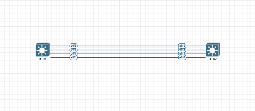
Switch D1 Configuration
- enable
- configure terminal
- hostname D1
- no ip domain lookup
- ip routing
- ipv6 unicast routing
- line con 0
- exec-timeout 0 0
- logging synchronous
- exit
- line vty 0 4
- privilege level 15
- password cisco 123
- exec-timeout 0 0
- logging synchronous
- login
- exit
- interface ethernet 0/2
- no switchport
- ip address 10.1.2.2 255.255.255.0
- ipv6 address fe80::d1:1 link-local
- ipv6 address 2001:db8:acad:1012::2/64
- no shutdown
- exit
- vlan 11
- name LOCAL_VLAN
- exit
- interface ethernet 0/0
- switchport mode access
- switchport access vlan 11
- no shutdown
- exit
- ip route 0.0.0.0 0.0.0.0 ethernet 0/2 10.1.2.1
- ip route ::/0 ethernet 0/2 2001:db8:acad:1012::1
Switch D2 Configuration
- enable
- configure terminal
- hostname D2
- no ip domain lookup
- ip routing
- ipv6 unicast routing
- line con 0
- exec-timeout 0 0
- logging synchronous
- exit
- line vty 0 4
- privilege level 15
- password cisco 123
- exec-timeout 0 0
- logging synchronous
- login
- exit
- interface ethernet 0/3
- no switchport
- ip address 10.1.3.2 255.255.255.0
- ipv6 address fe80::d1:1 link-local
- ipv6 address 2001:db8:acad:1013::2/64
- no shutdown
- exit
- vlan 11
- name LOCAL_VLAN
- exit
- interface vlan 11
- ip address 192.168.3.1 255.255.255.0
- ipv6 address fe80::d2:2 link-local
- ipv6 address 2001:db8:acad:3000::1/64
- no shutdown
- exit
- interface ethernet 0/0
- switchport mode access
- switchport access vlan 11
- no shutdown
- exit
- ip route 0.0.0.0 0.0.0.0 ethernet 0/2 10.1.3.1
- ip route ::/0 ethernet 0/3 2001:db8:acad:1013::1
Switch A1 Configuration
- enable
- configure terminal
- hostname A1
- no ip domain lookup
- line con 0
- exec-timeout 0 0
- logging synchronous
- exit
- line vty 0 4
- privilege level 15
- password cisco123
- exec-timeout 0 0
- logging synchronous
- login
- exit
- vlan 5
- name D1
- exit
- vlan 8
- name D2
- exit
- interface ethernet 0/0
- switchport mode trunk
- no shutdown
- interface ethernet 0/2
- switchport mode access
- switchport access vlan 5
- no shutdown
- exit
- interface ethernet 0/3
- switchport mode access
- switchport access vlan 8
- no shutdown
- exit
this setup may be a little different from your port configuration but ultimatly we have now configured our network with all the appropriate IP addresses on each interface and the appropriate vlans. Next we will go over setting up VRF-Lite to allow both customers to be able to create its own virtual routing table although their IP addresses overlap.
Part 2: Configure VRF-Lite and Interface addressing
In part 2 we will configure VRF-Lite on R1. The other devices require no additional configuration. First we will go over a couple different commands and their meaning to help better understand what’s going on each step of the way.
Create The required VRFs on R1
vrf definition names the configuration and enters vrf configuration mode. address-family is required to use either ipv4 and or ipv6.
- R1 (config)# vrf definition Customer_A
- R1 (config-vrf) address-family ipv4
- R1 (config-vrf-af) address-family ipv6
- R1 (config-vrf-af) exit
- R1 (config)# vrf definition Customer_B
- R1 (config-vrf) address-family ipv4
- R1 (config-vrf-af) address-family ipv6
- R1 (config-vrf-af) exit
next we will configure R1s ethernet 1/0 and ethernet 1/1 for the Customer_A network. On the interface we will use the command vrf forwarding to associate the vrf with the layer 3 interface and assign ip addresses to the interfaces.
- R1 (config)# interface ethernet 1/0
- R1 (config-if)# vrf forwarding Customer_A
- R1 (config-if)# ip address 10.1.2.1 255.255.255.0
- R1 (config-if)# ipv6 address fe80::1:1 link-local
- R1 (config-if)# ipv6 address 2001:db8:acad:1012::1/64
- R1 (config-if)# no shutdown
- R1 (config-if)# exit
- R1 (config)# interface ethernet 1/1
- R1 (config-if)# vrf forwarding Customer_A
- R1 (config-if)# ip address 10.1.3.1 255.255.255.0
- R1 (config-if)# ipv6 address fe80::1:4 link-local
- R1 (config-if)# ipv6 address 2001:db8:acad:1013::1/64
- R1 (config-if)# no shutdown
- R1 (config-if)# exit
Now lets configure Customer_B on the R1 Fast Ethernet 0/0 interface. This port will also be performing intervlan routing for vlan 5 and 8.
- R1 (config)# interface fastethernet 0/0.5
- R1 (config-subif)# encapsulation dot1q 5
- R1 (config-subif)# vrf forwarding Customer_B
- R1 (config-subif)# ip address 10.1.2.1 255.255.255.0
- R1 (config-subif)# ipv6 address fe80::1:1 link-local
- R1 (config-subif)# ipv6 address 2001:db8:acad:1012::1/64
- R1 (config-subif)# exit
- R1 (config)# interface fastethernet 0/0.8
- R1 (config-subif)# encapsulation dot1q 8
- R1 (config-subif)# vrf forwarding Customer_B
- R1 (config-subif)# ip address 10.1.3.1 255.255.255.0
- R1 (config-subif)# ipv6 address fe80::1:3 link-local
- R1 (config-subif)# ipv6 address 2001:db8:acad:1013::1/64
- R1 (config-subif)# end
Verify VRF-Lite configuration
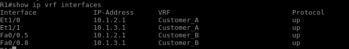
Lets now verify the VRF-Lite Configuration by issuing the command show ip vrf interfaces. This gives us the ability to see the status of each vrf and the ports its configured for.
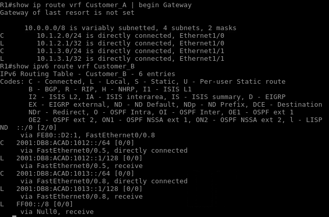
One benefit of vrf is the ability to have separate routing tables for each vrf configured. Using the command show ip route vrf vrf_name and show ipv6 route vrf_name we will be able to see the route table associated with each vrf and the routes that are created. Below you can see that we have directly connected routes for the Customer_A side and Customer_B side.
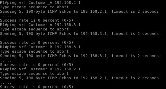
Lets verify that we can reach the next-hop within each vrf using the ping vrf vrf_name address command. As you can see we have full reachability from the image below within each vrf.

Part 3: Configure static routing for reachability inside each VRF-Lite configuration
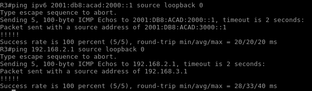
At the end of this part each respective vrf should be able to reach other parts of the network it was not able to reach before. Lets first verify that the distant networks are not reachable then configure some additional static routes for each needed vrf.
Verify the networks are not reachable
using the ping vrf vrf_name command try and ping one loopback address to the other. As you can see from our ping test we are not able to communicate with the other side. Lets now configure some static routing at R1 for each VRF
Lets configure static routing for each VRF
- R1 (config) ip route vrf Customer_A 192.168.2.0 255.255.255.0 255.255.255.0 ethernet 1/0 10.1.2.2
- R1 (config) ip route vrf Customer_A 192.168.3.0 255.255.255.0 255.255.255.0 ethernet 1/1 10.1.3.2
- R1 (config) ip route vrf Customer_A 2001:db8:acad:2000::/64 ethernet 1/0 2001:db8:acad:1012::2
- R1 (config) ip route vrf Customer_A 2001:db8:acad:3000::/64 ethernet 1/1 2001:db8:acad:1013::2
- R1 (config) ip route vrf Customer_B 192.168.2.0 255.255.255.0 255.255.255.0 fastethernet 0/0.5 10.1.2.2
- R1 (config) ip route vrf Customer_B 192.168.3.0 255.255.255.0 255.255.255.0 fastethernet 0/0.8 10.1.3.2
- R1 (config) ip route vrf Customer_B 2001:db8:acad:2000::/64 fastethernet 0/0.5 2001:db8:acad:1012::2
- R1 (config) ip route vrf Customer_B 2001:db8:acad:3000::/64 fastethernet 0/0.8 2001:db8:acad:1013::2
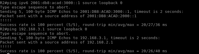
As you can see we now have full network reachability using VRF-Lite on R1. Any questions in regards to this lab feel free to comment or reach out.