VLAN Trunking protocol (VTP) manages the addition, deletion, and renaming of VLANs on the entire network from a single switch. Although not used as common in modern networks, VTP can be useful if managed correctly.
A VTP domain, also called a VLAN Management Domain, consists of trunked switches that share the same VTP domain name. A switch can only be in one VTP domain, and contents in the VLAN database are globally synchronized. VLAN information is only propagated if a domain name is specified and the trunks are setup between the devices.
There are 3 versions of VLAN Trunking Protocol available:
- Version 1
- Version 2
- Version 3
Along with 3 different version of VLAN Trunking Protocol there are 4 different modes.
| VTP Server | gives you the ability to create, modify, and delete VLANs. Other parameters can be configured such as VTP version and VTP pruning, for the entire VTP domain. VTP Servers advertise their VLAN configuration to others switches in the same VTP domain and synchronize their VLAN configuration with other switches based on advertisements from other trunk links. This mode is the default mode. VLAN configuration is stored in the flash:vlan.dat file. While VLANS are configured, the configuration does not show up in the running config. |
| VTP Client | This mode behaves like a VTP server and transmits and receives VTP updates on its trunks, but cannot create, change or delete VLANS. VLANS are created on another switch in the domain that is in server mode. In this mode VLANS are stored in the flash:vlan.dat. The Configuration of VLANS do not appear in the running config |
| VTP Transparent | VTP transparent switches do not participate in VTP. Transparent switches does not advertise, or synchronize its VLAN database. Transparent switches will forward received VTP messages under 2 circumstances: 1. The VTP domain name of the transparent switch is empty 2. Matches the domain name in the received VTP messages Transparent mode will store normal range VLAN configurations in the flash:vlan.dat are are also present in the running-config. If using extended ranges, they are stored in the flash:vlan.data if the switch is running VTP version 3. |
| VTP Off | Off mode functions the same as Transparent mode, except it does not forward VTP advertisements on trunks. |
Part 1: Build and Configure Basic Switch Settings
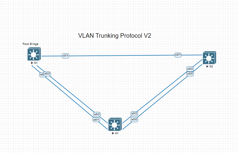
This part of the lab will consist of setting up the switches and connecting them all together. We are building off of the same lab setup that we done before from other labs so you can follow the same basic switch setup Here. The only thing you will omit is adding any VLANs from the lab setup, we will do that later in this lab.
If setting this lab up from scratch here are some of the basic resources needed:
- 3 Cisco switches (Cisco 3650 with new IOS or comparable release)
- 1 pc with a console cable to connect to the switches if using physical gear
- Eve-NG or GNS3 can be used to setup virtual environments to make it easier to spin new switches and routers up.
Part 2: Implement VLAN Trunking Protocol V2
Step 1. Verify VTP Status
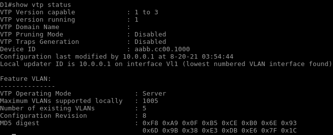
As we look at one of our switches we can see that the switch has the default VLAN Trunking Protocol setup. This switch is capable of running version 1, 2 and 3. All switches in a VTP domain must run the same version. When new configurations are made, the revision number increases. The VLAN database with the highest revision number is adopted by all the other switches in the management domain.
VTP messages are only sent out trunk ports to other switches.
Step 2. Configure and observe VTPv2 domain operations
Configure D1 for server mode and set the VTP domain name and Version to 2. To prevent unauthorized vlan database propagation we are going to implement a password. With the password set, VTPv2 will not allow other switches to automatically learn the domain name.
- D1# config t
- D1 (config)# vtp domain ccnp
- D1 (config) # vtp version 2
- D1 (config) # vtp mode server
- D1 (config) # vtp password cisco
On D1 create a new VLAN and assign it to an open port. Name the vlan secondvlan. We will verify the VTP status again and notice that the revision number has changed.
- D1# config t
- D1 (config)# vlan 2
- D1 (config-vlan) # name secondvlan
- D1 (config-vlan) # exit
- D1 (config) #interface e 0/0
- D1 (config-if) #switchport mode access
- D1 (config-if) #switchport access vlan 2
- D1 (config-if) #no shutdown
- D1 (config-if) #end
- D1# show vlan brief
- D1 (config) show vtp status
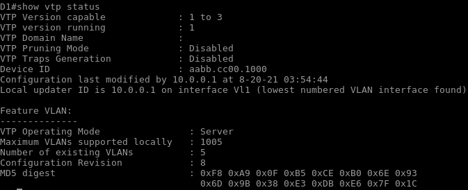
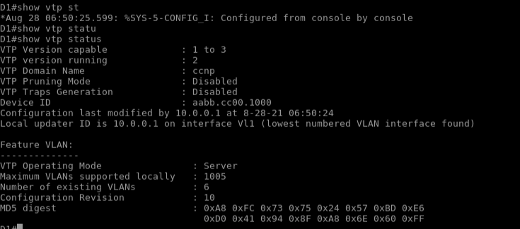
To get vtp working and setup you first want to go and configure the same configuration on your other switches. The vtp domain name, password and version must all be the same. Extended VLAN’s are not propagated via VTP version 2. To demonstrate the drawbacks of the VLAN Trunking Protocol, we are going to remove VLAN 2 from switch A1.
- A1# config t
- A1 (config)# no vlan 2
If you go back to switch D2 you will see that VLAN 2 no longer exist. This is the main drawback to VTP version 2. Without careful planning and control, removing a VLAN from a switch can bring entire portions of a network down.
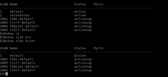
Now lets put in some measures to prevent other switches from being able to create VLAN’s. First lets go back to switch D1 and put the second VLAN back in place. To prevent Switches from being able to create VLAN’s, first you must set the VLAN Trunking Protocol mode to client. After you set the switch to client mode attempt to create another VLAN.

On Switch D2 lets set the VTP mode to transparent and attempt to create a VLAN. As you will see in transparent mode VLANS are not learned or propagated to other switches.

Now that you see the advantages and disadvantages of Vlan Trunking Protocol, hopefully you can find the use for it in your network. Next we will go over and talk about VLAN Trunking Protocol V3.
