The (STP) Spanning Tree Protocol Explained in simple terms is a link management protocol that enables path redundancy while also preventing undesired network loops. As far as Ethernet networks are concerned, only one active path between two stations can exist if they are to function effectively. A variety of factors can lead to loops in a network. Network loops are caused by levels of redundancy.
The Spanning Tree Protocol works out of the box with the default values. Although the topologies may be loop-free the structure may not align with what your network needs are. The Spanning Tree Protocol out of the box is vulnerable to several different scenarios such as the root bridge being taken over or a loop introduced into the network.
Below Spanning Tree Protocol Explained in a lab format will help show you various way to help bend the logical spanning tree protocol topology to meet your network needs.
Part 1: Implement and observe Various Spanning Tree Protocol Tuning Methods
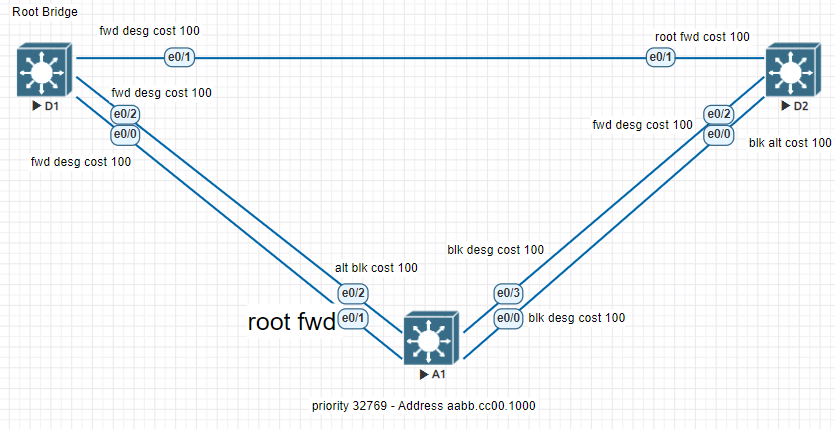
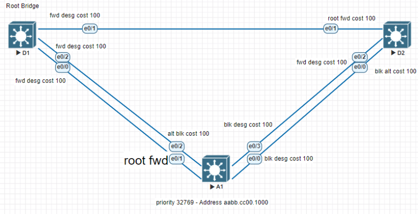
Here’s how to set up the appropriate network configuration so that you can walk through the information described below. The terminology can be used in your lab. Drawing out your configuration, as seen in the figure above, is always helpful in evaluating where improvements can be made.
step 1. Controlling the root bridge
The root bridge is elected based on the lowest Bridge ID (consists of the Priority, Extended system ID equal to the vlan id, and the base mac address value. The priority and extended system IDs are usually identical on default setups of spanning tree in a network. With that being said the root bridge’s mac on a network is typically smaller, which may not be the desired choice in some networks.
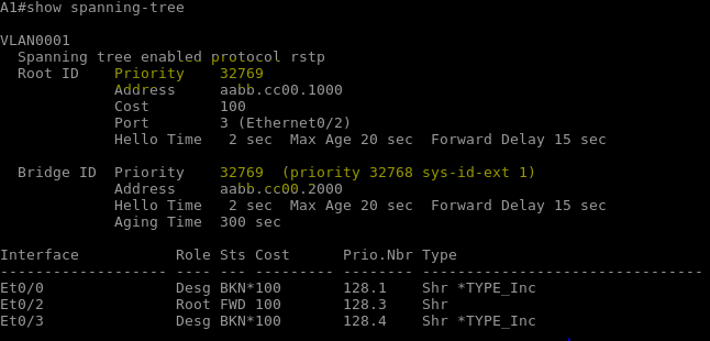
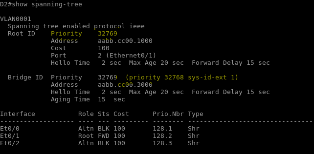
There are two easy ways to change the location of the root bridge:
- Using the command “Spanning-tree vlan 1 priority 4096”
- The “Spanning-tree vlan 1 root {primary | secondary}” command to set an automatic priority value
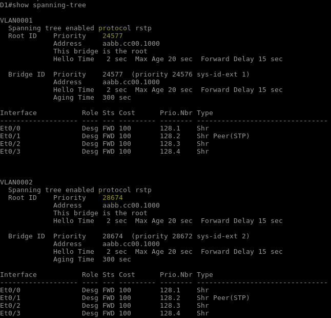
When using a priority command the value must be a increment of 4096. The root primary command lowers the local bridge’s priority to 24576. The primary command only tries to lower the priority as much as needed to win the root election. The secondary command will set the priority to 28672.
Lets set some commands to set the primary and secondary root for vlan 1 and 2 on switch D1.
D1(config)# spanning-tree vlan 1 root primary
D1(config)# spanning-tree vlan 2 root secondary
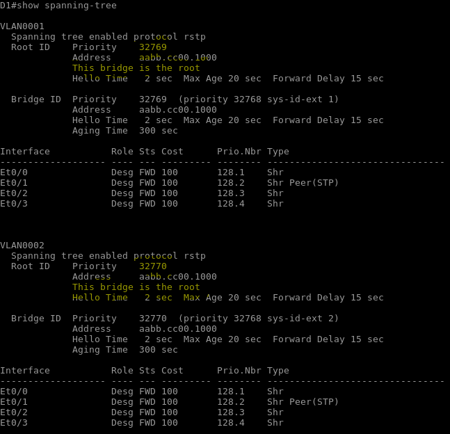
Step 2. Adjusting port cost values to impact root and designated port
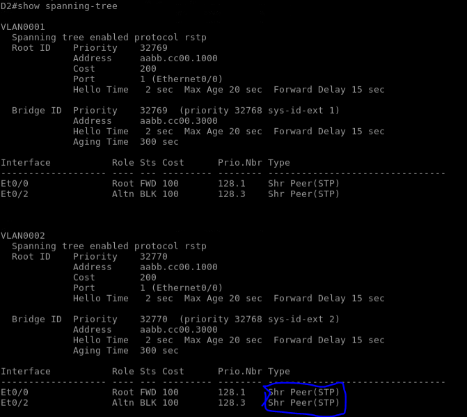
This lab configuration has 2 paths between switch A1 and the root bridge for each vlan. path and port cost are evaluated on the links to determine the shortest path to the root bridge. Determine your root ports and blocked ports using the command “show spanning-tree vlan” and “show spanning-tree blockedports”
Change the port cost on anther port besides the main root port to change the path. Doing this during a live production network can cause downtime. On the port your changing issue the command “spanning-tree cost (numeric value). Root cost and Port cost are different in a since the port cost is the cost associated with the physical port. The root cost is the cost it takes to get to the root. If you have equal cost paths to the root, the loest port ID is selected as root port.
Step 3. implement spanning tree portfast
New switches connected to the network have to make sure they will not create a loop. Convergence time takes 30 seconds. Devices such as workstations, printers, etc do not need that amount of time to start forwarding traffic. On devices connected to a single workstation configure devices with the “spanning-tree portfast” to remove the 30 second wait before it forward frames.
