Multiple Spanning Tree protocol (MST) is an open protocol derived from rapid spanning tree protocol. MSTP runs a number of VLAN-independent STP instances (representing logical topologies) instead of one for each VLAN, and then the administrator maps each VLAN to the most appropriate logical topology (STP instance). The number of STP instances is maintained to a bare minimum (to save switch resources), but the network capacity is better utilized by utilizing all potential VLAN traffic pathways.
Part 1: implement and observer multiple spanning tree
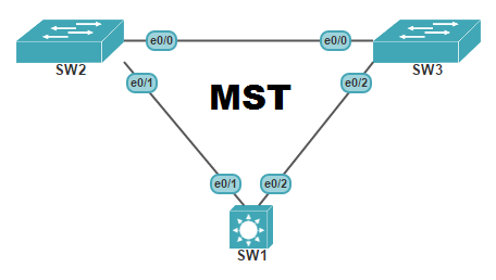
Lets start by configuring a basic network setup for this more advanced spanning tree setup. We will be using the lab configured in our previous post and continue forward with that network design.
step1: switch D1 and D2 configure Multiple Spanning Tree.
D1 (config)# spanning-tree mode mst
Both switches you will see that the spanning tree output is simplified
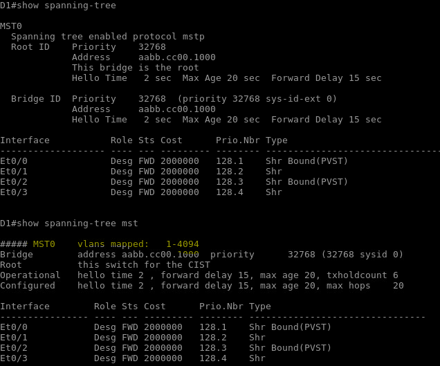
Multiple spanning tree has the same basic behavior as spanning tree:
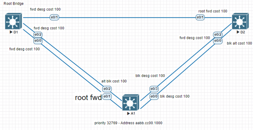
- A root bridge must be selected
- Then root ports
- Finally best paths to the root bridge
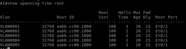
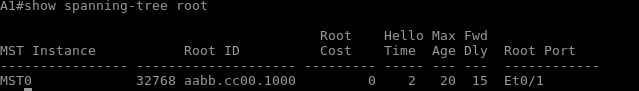
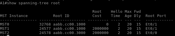
D1 has been selected as root bridge based off default priority and lower mac address. Although your root may be different the rules remain the same. Although (MST) is configured on both D1 and D2. issuing the command “show spanning-tree root” on switch A1 shows multiple spanning tree instances. With the addition of more vlans, this could lead to more cpu and ram usage on the switches causes more network issues.
Switch A1 configured with MST shows the following output like the rest of the switches.
Part 2: Configuring Basic Multiple Spanning Tree Operations
Now that we have MST configured on all three switches, we will further configure and tune to support the unique requirements
step 1:
Lets start by creating and verifying mst on each switch. With the full configuration completed on all the switches we will help reduce the load of the spanning tree protocol while still providing a spanning tree topology for groups of VLANS. Complete the following task on switch D1:
- Enter mst config mode using spanning-tree mst configuration
- D1 (config)# spanning-tree mst configuration
- Configure a mst region name
- D1 (config-mst)# name ccnpmst
- Create a revision number
- D1 (config-mst)# revision 1
- Configure instance 1 to include VLAN 2
- D1 (config-mst)# instance 1 vlan 2
- Configure instance 2 to include VLAN 4
- D1 (config-mst)# instance 2 vlan 4
- Commit the changes and lets verify the new configuration
- D1 (config-mst)# exit
- D1 (config)# end
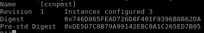
- D1# show spanning-tree mst
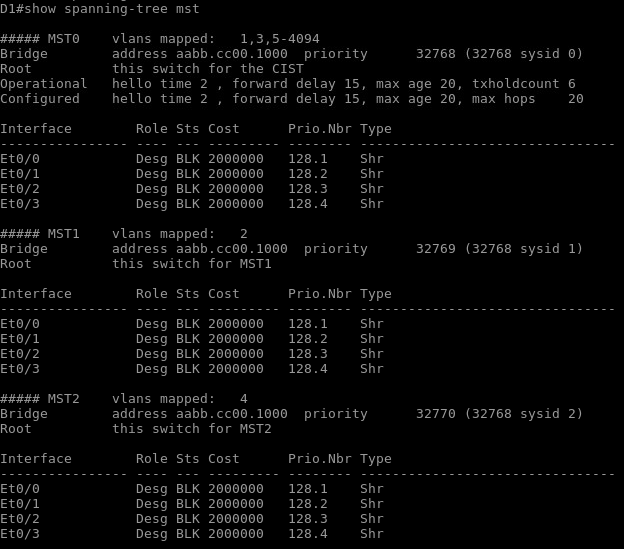
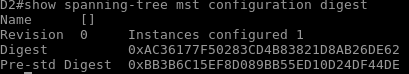
The mst configuration does not propagate to other switches. With that being said each switch not configured will show different digest information.
Lets add another revision number and add VLAN 3 to instance 1 and VLAN 5 to instance 2:
- D1(config-mst)# revision 2
- D1(config-mst)# instance 1 vlan 3
- D1(config-mst)# instance 2 vlan 5
step 2 manipulate the root bridge:
All the switches are configured with mst and using the same root bridge. The 2 ways to manipulate the configuration of the root bridge is by using the “spanning-tree mst instance-id priority value” command manually or the “spanning-tree mst instance-id root ( primary | secondary )” command. If using the priority command you must set the ID in multiples of 4096 and the primary and secondary command will automaticall adjust the priority number to become less than the current root bridge or just a little higher than the primary if using the secondary command.
Lets modify switch D1 and D2 so that D1 is the primary root bridge for instance 1 and D2 is primary for instance 2. D1 will be secondary for instance 2 and D2 secondary for instance 1.
- D1(config)# spanning-tree mst 1 root primary
- D1(config)#spanning-tree mst 2 root secondary
- D2(config)#spanning-tree mst 2 root primary
- D2(config)#spanning-tree mst 1 root secondary
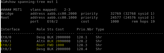
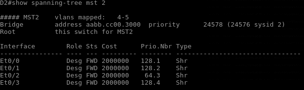
step 3 adjust port cost:
Now that we have the primary and secondary root bridges designated, the next steps is adjusting the root and designated port based on port cost values. Non-root bridges can be adjusted to a cost between 1 and 200,000,000. Port priority values between 0 and 240 in increments of 16. These changes can have an impact to downstream switches as well. Switch A1 interface e 0/2’s port cost will change to 1000.
- A1(config)# interface e 0/2
- A1(config-if)# spanning-tree mst 1 cost 1000
- A1(config-if)# exit
step 4 adjust port priority numbers:
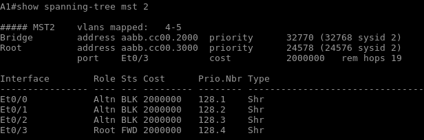
The next method to impact root port selection is adjusting the port priority value in increments of 16. When you have 2 ports with equal cost paths to the root bridge, the lower port ID will be selected as the root port. As we can see for switch A1 in the spanning tree mst 2 instance, port 0/0 took the root port over 0/3.
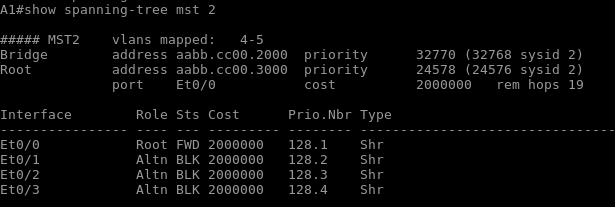
Lets modify the port priority of port e 0/2 on switch D2 to change the preferred port.
- D2# config t
- D2(config)# interface e 0/2
- D2(config-if)# shutdown
- D2(config-if)# spanning-tree mst 2 port-priority 64
- D2(config-if)# no shut
- D2(config-if)# exit
Now that we have the priority changed on switch D2 we can check and see that the new root port has changed on switch A1
Multiple Spanning Tree protocol is a great protocol to add to a growing network. As you start to introduce more VLANs into your network, keeping your switch resources under control can be the difference between more downtime and less uptime between devices.