I covered the fundamentals of Cisco VLAN Trunking Protocol in a previous article (version 1 and 2). VTP version 3‘s primary purpose is to synchronize VLANs, but it also includes a number of optional features. It’s been around for a long, but it wasn’t supported on Cisco Catalyst Switches until recent IOS releases.
In this part of the lab we will configure VLAN Trunking Protocol (VTP) to operate across the rest of the switches using the network that we configured in the previous labs. VTP Version 3 provides some significant benefits to to the network:
- It is now possible to build a primary server. All VTP server switches in versions 1 and 2 are the same. Any of them can change the state of VLANs by adding, removing, or renaming them. Only the primary server can accomplish this in VTP version 3. The basic function of the server is to be in a running state. This status is requested in privileged EXEC mode and released when another switch tries to become the primary server or the switch is reloaded.
- The VTP password can be hidden in VTP version 3. The “Show vtp password” command in VTP Version 1 or 2 would display the password in plaintext.
- Extended VLANS, which have numbers between 1006 and 4094, can be propagated using VTP version 3. All switches must be in Transparent or Off mode to support these VLANs with VTP version 1 or 2, and the VLANs must be established manually on a switch-by-switch basis.
- VTP version 3 only supports pruning for normal range VLANS
- VTP Version 3 supports propagating Private VLAN information. As with extended-range VLANs, the lack of PVLAN support in VTP version 2 required all switches be in Transparent mode and manually configured at each switch
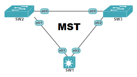
- VTP version 3 added support for opaque databases. In other words, VTP version 3 can support more than just the VLAN database between switches. The only option at this time is to share the Multiple Spanning Tree (MSTP) database.
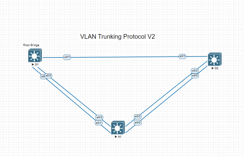
Step1. Configure and verify VLAN Trunking Protocol Version 2 on D1
VTP Version 3 is backwards compatible with VTP version 2 for normal range VLANs only; at the boundary of the two protocols, a VTP version 3 switch will send out both version 3 and version 2 compatible messages. Version 2 messages received by a version 3 switch are discarded.
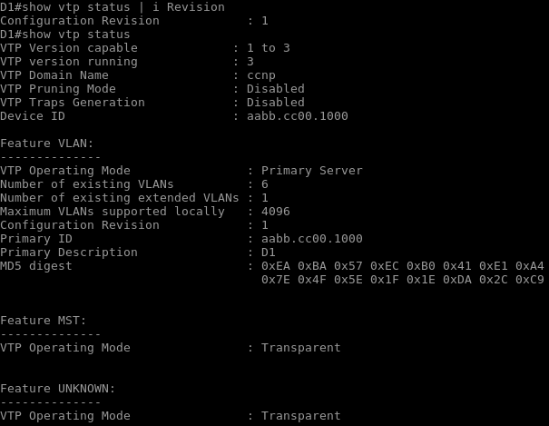
On D1, change the VTP version to version 3 and verify the change. As you will see the number of VLANS supported locally has increased as well.
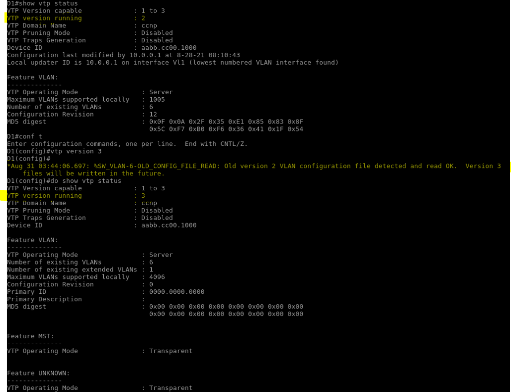
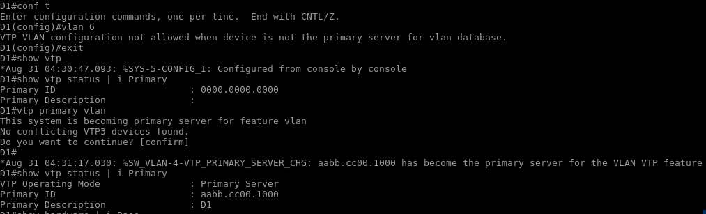
On D1, try and create VLAN 6. You should not be allowed to do so. Examine the output of “Show vtp status”, you will see that the identification of the primary server is blank.
- D1# show vtp status | i Primary
- D1# vtp primary vlan
- D1# show vtp status | i Primary
In this order you will be able to check the current status of the primary VTP VLAN and set this switch as the Primary
Step 2. Configure Additional VLANs and Verify VTP Revision Status
Now you see that VTP version 3 is working now that it allows for extended range VLANs while in server mode, it is sending VTP version 2 compatible messages at the domain boundary, and D2 is passing those messages along. Comparing the VTP status of switch A1 and D1 you will see that the revision number is far less than needed to propagate changes to switch A1.
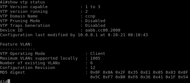
Although you can see that version 3 shows more output than version 2 the revision number for Switch A1 is very much higher than D1. In order to get a higher revision number we must make enough VLAN changes to get above that number which could be doing something as simple as changing a VLAN name. Lets create a couple VLANS to get above that 12 revision number for switch D1.
- VLAN 6, named sixthvlan
- VLAN 7, named seventhvlan
- VLAN8, named eighthvlan
- VLAN9, named ninthvlan
- VLAN10, named tenthvlan
- VLAN11, named elevenvlan
- VLAN12, named twelvevlan
- VLAN13, named thirteenvlan
- VLAN14, named fourteenvlan
- VLAN15, named fifthteenvlan
- VLAN16, named sixteenvlan
- VLAN17, named seventeenvlan
- VLAN18, named eighthteenvlan
Now if we check Switch A1 we will now see that the switch has learned all of the VLANs that switch D1 created. D2 will not be able to learn any of the new VLANs because its in Transport mode. On D1 lets create VLAN 2600 and lets see what happens on Switch A1.
- D1# config t
- D1 (config)# vlan 2600
- D1 (config-vlan)# name vlanextended
- D1(config-vlan)# end
- A1# show vlan brief
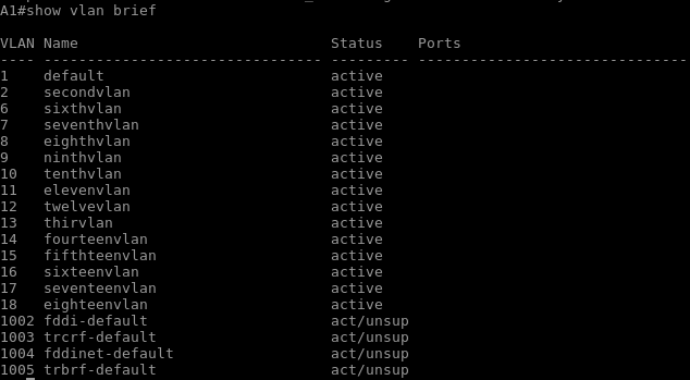
VLAN Trunking Protocol Version 2 does not support learning extended VLANS as you can see so we will have to upgrade Switch A1 and D2 to VTP version 3.
Step 3. Configure VLAN Trunking Protocol Version 3 on Switch A1 and D2
Lets configure D2 and A1 to operate using VTP version 3.
- D2# config t
- D2 (config)# vtp version 3
- D2 (config)# end
- A1# config t
- A1 (config)# vtp version 3
- A1 (config)# end
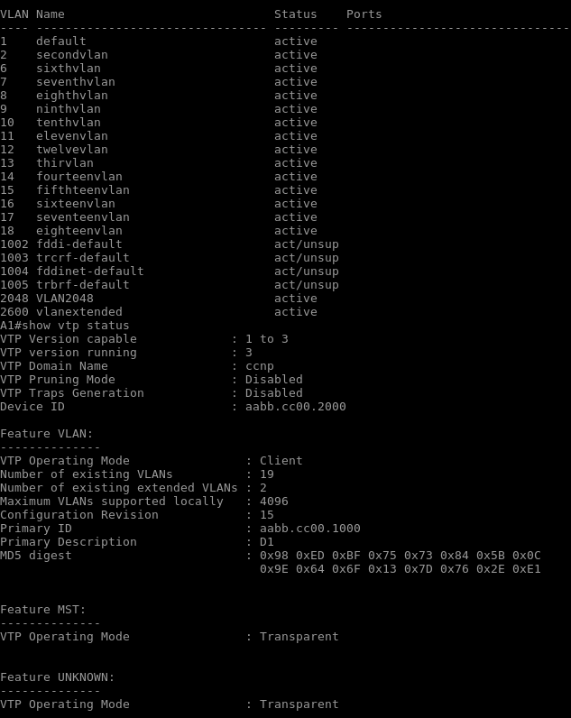
Not only has VTP version been updated to version 3 we can now see from the picture above that the new extended VLANs have now been propagated. VTP status on switch D2 will show that the revision number has not changed and it still is not propagating new VLANs.