The Etherchannel Configuration implemented in this guide will explore various methods of Link Aggregation, which will combine the connections into single logical channel group. Port Aggregation Protocol (PAgP), is a Cisco Etherchannel Protocol and LACP is an open standard version of Etherchannel. These protocols are signaling protocals that allow two switches to negotiate the use of selected ports as a member of a single Etherchannel bundle.
Etherchannel allows up to eight redundant links into one logical link. In this Etherchannel Configuration Guide we will use Etherchannel to refer to logical bundling of multiple physical links and Port-channel to refer to a virtual interface that represents an Etherchannel Bundle in the Cisco IOS Configuration.
Objectives
- Part 1: Build the network and explore Dynamic Trunking Protocol
- Part 2: Configure Device Settings
- Part 3: Configure Static Etherchannel
- Part 4: Etherchannel Configuration using PAgp
- Part 5: Etherchannel Configuration using LACP
Part 1: Configuring and Exploring Dynamic Trunking Protocol
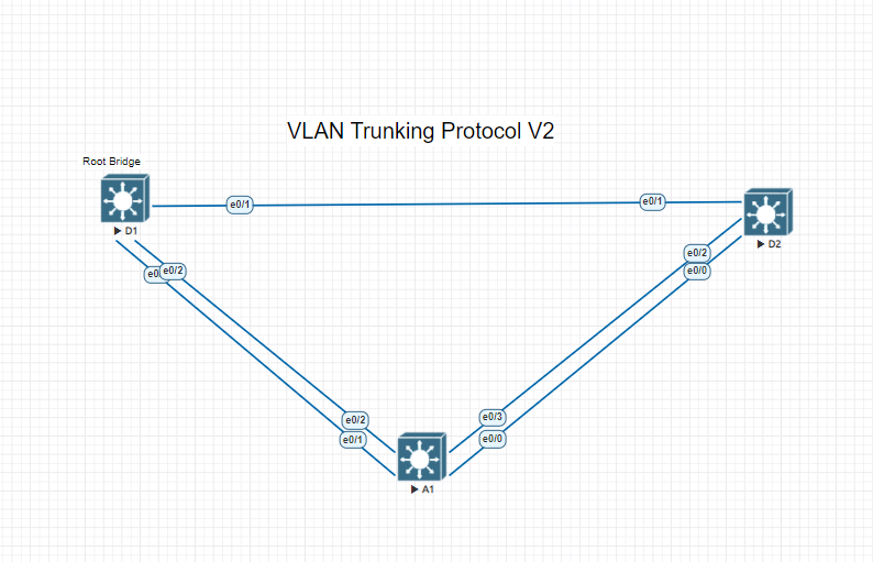
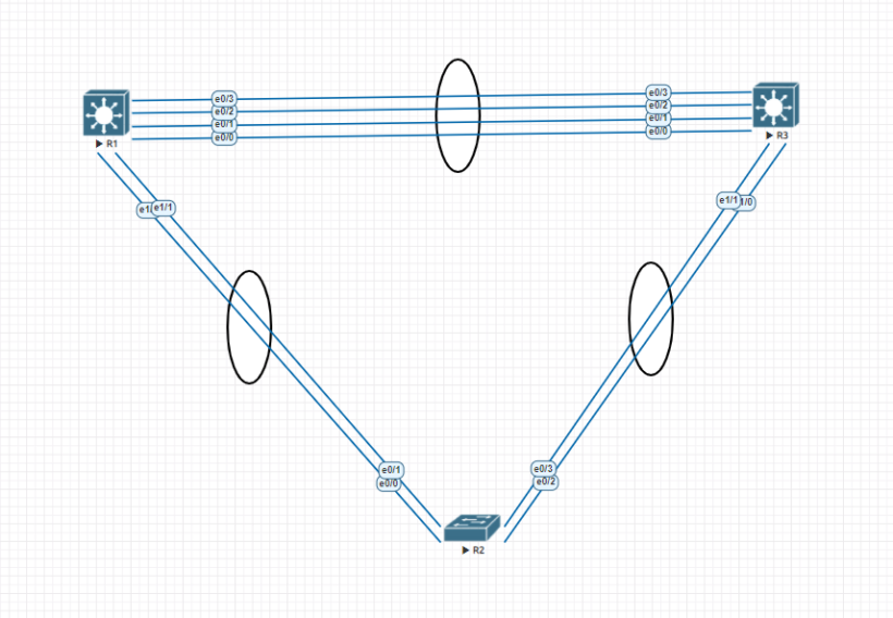
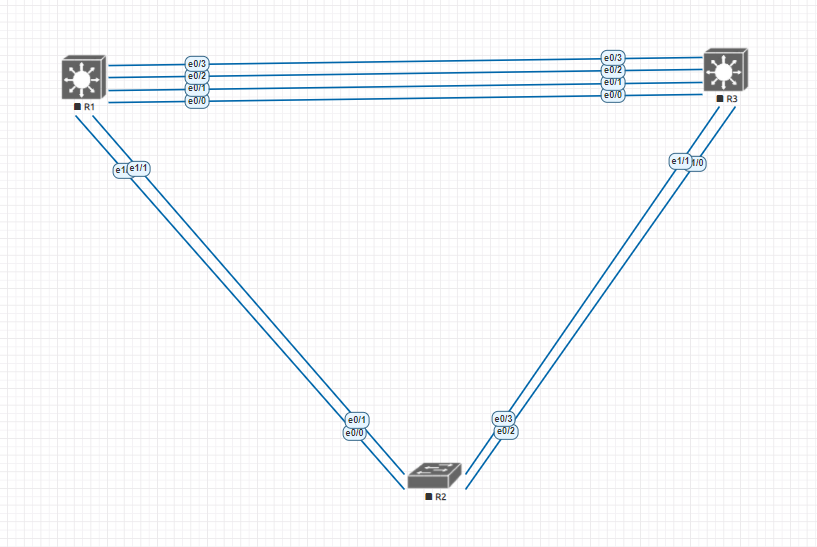
Whether your using packet tracer, Eve-Ng or GNS3 your configuration should look like the image below to walk step by step in this lab.
Step 1: Lets examine the default port status and manipulate DTP
The switches in our configuration are in a default setup so the connection defaults to an access port on VLAN 1. Lets take a look at R1’s Output using the command “show interfaces ethernet 1/0 switchport” and the same on Switch R2 on port Ethernet 0/0.
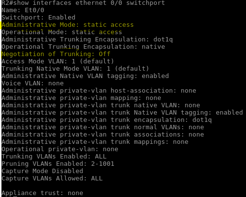
Examining the output we can see that the administrative mode is set to static access and the negotiating of trunking is off. DTP is used by Cisco switches to automatically negotiate whether the port should be in access or trunk mode. DTP is not secure so which means that a device could send false DTP packets and cause a switchport to become an unauthorized trunk port. This will give an attacker access to all vlans. Lets configure all of the switches ports as trunk ports.
Switch R2
- R2# conf t
- R2 (config)# interface range ethernet 0/0-3
- R2 (config-if-range)# switchport trunk encapsulation dot1q
- R2 (config-if-range)# switchport mode trunk
- R2# conf t
- R2 (config)# interface range ethernet 1/0-3
- R2 (config-if-range)# switchport trunk encapsulation dot1q
- R2 (config-if-range)# switchport mode trunk
Switch R1
- R1# conf t
- R1 (config)# interface range ethernet 0/0-3
- R1 (config-if-range)# switchport trunk encapsulation dot1q
- R1 (config-if-range)# switchport mode trunk
- R1# conf t
- R1 (config)# interface range ethernet 1/0-3
- R1 (config-if-range)# switchport trunk encapsulation dot1q
- R1 (config-if-range)# switchport mode trunk
Switch R3
- R3# conf t
- R3 (config)# interface range ethernet 0/0-3
- R3 (config-if-range)# switchport trunk encapsulation dot1q
- R3 (config-if-range)# switchport mode trunk
- R3# conf t
- R3 (config)# interface range ethernet 1/0-3
- R3 (config-if-range)# switchport trunk encapsulation dot1q
- R3 (config-if-range)# switchport mode trunk
Part 2: Static Etherchannel Configuration
Now that we have all of the ports configured as trunk ports on the switches we can proceed with the Etherchannel Configuration. Etherchannel should be set with a negotiation protocol for best practices but the focus of this part will be to establish the process for creating and modifying the etherchannel bundle.
Step 1: Configure and verify trunking between R2 and R3
configure the ports interconnecting R2 and R3 as static trunk ports with the “switch-port nonegotiate” if not already and then configure the channel group
- R2# config t
- R2 (config)# interface range ethernet 0/2-3
- R2 (config-if-range)#channel-group 1 mode on
- R3# config t
- R3 (config)# interface range ethernet 1/0-1
- R3 (config-if-range)#channel-group 1 mode on
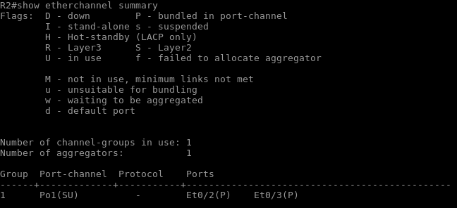
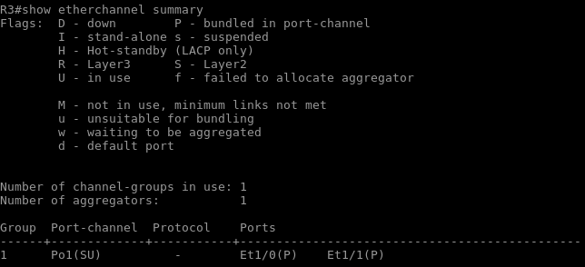
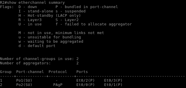
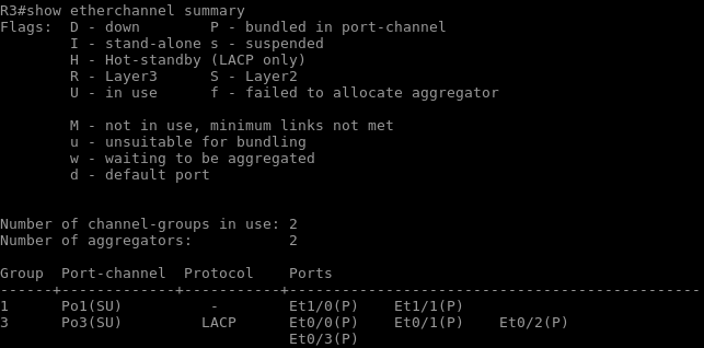
Once the channel group comes up you should get a message such as “*Sep 3 05:20:44.597: %LINEPROTO-5-UPDOWN: Line protocol on Interface Port-channel1, changed state to up”. Issue the command “Show etherchannel summary” and you will see that both switches now have multiple ports bunlded together.
Changes to the etherchannel configuration must must be made at the port-channel level. Changes directly on the member interfaces may create synchronization issues that may cause the group to fail or underperform.
- On R3 and R2, create VLAN 999 named NATIVE_VLAN.
- on R3 and R2, modify the port-channel 1 so that it uses VLAN 999 as the native vlan.
- R2# config t
- R2(config)# interface port-channel 1
- R2(config-if)# switchport trunk native vlan 999
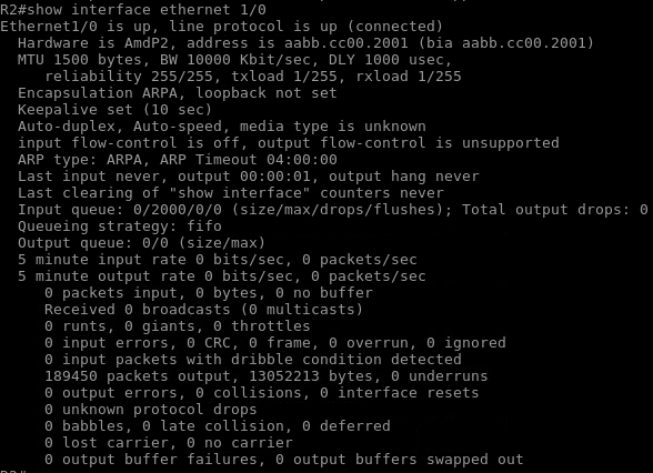
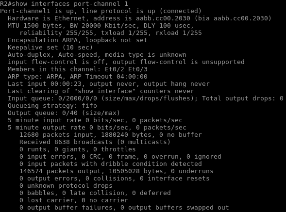
we can see from the image above in the bandwidth (BW) column we not only get added redundancy from the additional link we get additional speed of 20000 kbit/s as long as the other side is matched with the same speed and configuration.
Part 3: Etherchannel Configuration using PAgP
Cisco’s proprietary Port Aggregation Protocol (PAgP) is only compatible with Cisco switches. Desirable and Auto are the two modes of the protocol. These modes work in the same way as Dynamic Trunking Protocol modes do. Desirable actively expresses a wish to create an EtherChannel bundle, whereas auto passively accepts a bundle if the switch on the other end does. The bundle will not form if both ends are set to auto.
Step1: Configure trunking and PAgP between R1 and R2
- R1 (config)# interface range ethernet 1/0-1
- R1 (config-if-range)# switchport trunk encapsulation dot1q
- R1 (config-if-range)# switchport mode trunk
- R1 (config-if-range)# channel-group 2 mode desirable non-silent
- R2 (config)# interface range ethernet 0/0-1
- R2 (config-if-range)# switchport trunk encapsulation dot1q
- R2 (config-if-range)# switchport mode trunk
- R2 (config-if-range)# channel-group 2 mode desirable non-silent
As you can see in the image below we now have active Etherchannel configurations using PAgP. Changes to the Etherchannel configuration must be made at the port-channel level

Part 4: Etherchannel Configuration using LACP
There are two types of the Link Aggregation Control Protocol, or LACP: Active and Passive. Passive mode passively agrees to bundle if the switch at the other end starts it, whereas Active mode actively indicates a wish to form an Etherchannel bundle. The bundle will not create if both ends are configured in passive mode.
Step 1: Configure LACP between R1 and R3
- R1 (config)# interface range ethernet 0/0-3
- R1 (config-if-range)# switchport trunk encapsulation dot1q
- R1 (config-if-range)# switchport mode trunk
- R1 (config-if-range)# channel-group 3 mode active
- R3 (config)# interface range ethernet 0/0-3
- R3 (config-if-range)# switchport trunk encapsulation dot1q
- R3 (config-if-range)# switchport mode trunk
- R3 (config-if-range)# channel-group 2 mode active
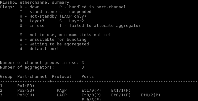
We’ve now set up three separate Etherchannel Configuration kinds. DTP is a type of static Etherchannel configuration that uses the mode on command to group many ports into a bundle. The Desirable and Auto commands on the defined Channel Group can be used to negotiate PAgP, which is a Cisco proprietary protocol. And LACP, which may be configured using the “Active” or “Passive” configurations on the channel group, is the open standard available to most vendors.